Hey,
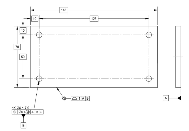
Long time lurker, first time poster. I'm looking to update some of my older drawings to be compliant with Y14.5-2009. To my knowledge, I'm the only person at my company with knowledge of the GD&T symbols and system (recently certified as a Technologist), so I don't have anyone to run this past--I was hoping I could have a draft checked. This is a generic base plate for an Instron universal tester. The only critical feature is the bolt pattern, 4X M6 X 1 on a 125 X 50 rectangle. I don't know the position tolerance of the tapped holes, so I started with a 6.4 clearance hole and my own position tolerance of 0.4 at MMC. I have opted to make the pattern its own datum, from which future holes/slots can be located relative to the DRF the pattern creates. We usually make the base plates from 6061 stock, so flatness is already controlled to a point we are satisfied; the the outer dimensions, and spacing of the pattern to the edges, are less critical.
Thoughts? In hindsight, my position tolerance for the holes may be off (it's double the fixed fastener tol equation), but I'm curious what feedback I receive.
Thank you in advance!
Kevin

