Continue to Site

Eng-Tips is the largest engineering community on the Internet

Intelligent Work Forums for Engineering Professionals

  • Congratulations waross on being selected by the Eng-Tips community for having the most helpful posts in the forums last week. Way to Go!

Please critique my first GD&T drawing 1

Status
Not open for further replies.

KT12345

Mechanical
Aug 6, 2021
6
Hey,

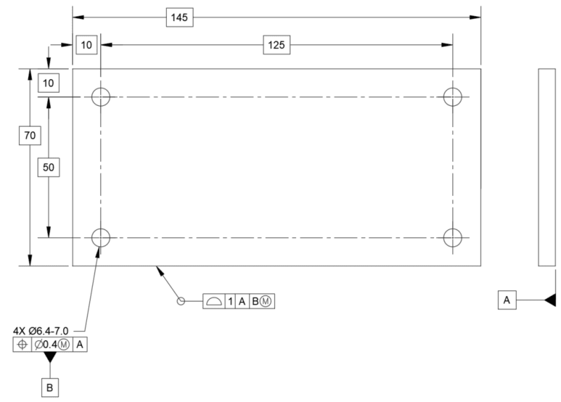
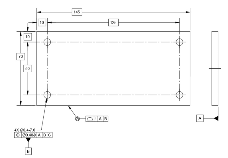
Long time lurker, first time poster. I'm looking to update some of my older drawings to be compliant with Y14.5-2009. To my knowledge, I'm the only person at my company with knowledge of the GD&T symbols and system (recently certified as a Technologist), so I don't have anyone to run this past--I was hoping I could have a draft checked. This is a generic base plate for an Instron universal tester. The only critical feature is the bolt pattern, 4X M6 X 1 on a 125 X 50 rectangle. I don't know the position tolerance of the tapped holes, so I started with a 6.4 clearance hole and my own position tolerance of 0.4 at MMC. I have opted to make the pattern its own datum, from which future holes/slots can be located relative to the DRF the pattern creates. We usually make the base plates from 6061 stock, so flatness is already controlled to a point we are satisfied; the the outer dimensions, and spacing of the pattern to the edges, are less critical.

Thoughts? In hindsight, my position tolerance for the holes may be off (it's double the fixed fastener tol equation), but I'm curious what feedback I receive.

Thank you in advance!

Kevin

base_plate_ktjo8m.png
 
Replies continue below

Recommended for you

Position to A|B|C| which is datum feature B, does not make sense.

 
Greenimi,

You're right. I originally had the left and top edges called out as datums. I forgot to remove that reference in the FCF. Thanks!
 
Where is Datum C?

"Know the rules well, so you can break them effectively."
-Dalai Lama XIV
 
You may use the (4)holes pattern as secondary datum feature, it will restricts the part movement in three directions. It serves as both a secondary and tertiary datum features, therefore, no tertiary datum feature is required and you can remove the tertiary datum C from your FCF callout.

|POS|Ø0.4M|A|BM| edited to |POS|Ø0.4M|A|
and add |profile|1|A|BM|

Normally, When a hole pattern is used as a datum feature, it is almost always referenced at MMC(edited to MMB) as shown above.

Season
 
Thank you, everyone, for your feedback! I have made the recommended changes. I also revised the profile call-out from ALL OVER to ALL AROUND.

base_plate_bhu6g6.png


KT
Medical Devices
GDTP-2009 Technologist
 
From your 1st posted sketch, secondary datum B is attached to the 4 holes pattern position’s FCF callout, that’s why I said you may use the 4 holes pattern as your secondary datum feature.

From the 2nd sketch you posted, there is only one primary datum feature referenced, that means it intend to control only the spacing and orientation of the holes in a pattern relative to datum plane A, and the tolerance of position does not control the location of the hole pattern. But, the holes dimensions are clearly defined as basic dimension from the edges, so this is contradictory.

When a hole pattern is used as a datum feature, it does not have to be located from the outside edges of the part. The outside edges of the part can be defined from the hole pattern and toleranced with a profile control.

I originally had the left and top edges called out as datums.

So, you may need to revise the sketch to your original intention

Season
 
SeasonLee said:
that means it intend to control only the spacing and orientation of the holes in a pattern relative to datum plane A, and the tolerance of position does not control the location of the hole pattern. But, the holes dimensions are clearly defined as basic dimension from the edges, so this is contradictory

Sorry season, I do not see anything wrong with the second sketch. Not sure what you are talking about as being contradictory.
You do need basic dimensions from the holes to the edges because you are defining where the edges are (from the holes)

Also, I do not agree with your statement "and the tolerance of position does not control the location of the hole pattern". I would say it is the other way around:
and the tolerance of position does control the location of the hole pattern
 
greenimi said:
Sorry season, I do not see anything wrong with the second sketch. Not sure what you are talking about as being contradictory.
You do need basic dimensions from the holes to the edges because you are defining where the edges are (from the holes)

Also, I do not agree with your statement "and the tolerance of position does not control the location of the hole pattern". I would say it is the other way around: and the tolerance of position does control the location of the hole pattern

I was in the middle of typing my response, which was pretty similar to yours. I didn't see a substantial difference between what I am trying to do and, say, Figure 4-39 from the (2009) standard:

fig_4-39_nlmli4.png


KT
Medical Devices
GDTP-2009 Technologist
 
greenimi said:
and the tolerance of position does control the location of the hole pattern

The position callout of the 4 holes pattern on the 2nd sketch : |POS|Ø0.4M|A|

There is only one primary datum A referenced, so only 3 DOFs(Z,u,v) are constrained, X and Y direction still free to move. In this case, the position tolerance only control the spacing between the holes and the orientation relative to the datum plane A.

Would you please talk more on how to control the hole pattern location.

Season
 
Season,

The holes pattern is secondary datum feature. You don't need to control its location from primary. You need to control other features ( the edges, the sides) location FROM it. ( that's why the OP is using profile all around)

(The mutual relationship between the holes is controlled by the position, that's why we are using position and not perpendicularity; I hope we agree with this).

It is the same idea and concept with 3-2-1 planar datum features- classic coordinate system. Primary datum feature does need only flatness (for example). The secondary datum feature needs only orientation (lets say perpendicularity), and does not have a location relationship to primary. When the tertiary datum features came along then again an orientation needs is required (not the location one)
 
SeasonLee said:
There is only one primary datum A referenced, so only 3 DOFs(Z,u,v) are constrained, X and Y direction still free to move.

By the way, I do not agree with this statement.
A hole by itself will stop 3 DOFs, but 2 holes (or multiple holes) will stop 5 DOFs.
 
The outside edges of the part can be defined from the hole pattern and toleranced with a profile control.

This is what I mentioned earlier, how come I forgot it when I talked about the 4 holes pattern assigned as a secondary datum feature, I forgot the basic dimension from the edges is to define the true profile of the edges. I stand corrected. May be I am too tired today.

greenimi said:
Also, I do not agree with your statement "and the tolerance of position does not control the location of the hole pattern". I would say it is the other way around:
and the tolerance of position does control the location of the hole pattern

Thanks for your replies, but I am not convinced by your replies at this point, I found a quite similar example from Fundamentals of GD&T 2018 SAE page 306, here is the snapshot:

2021-08-10_224802_hd43as.jpg


As underlined states: the position tolerance…it does not tolerance the location of the pattern. That is same as I said: the tolerance of position does not control the location of the hole pattern.

Season
 
SeasonLee,
I agree with what you said, but the difference between SAE's drawing and OP's is that the former does not have the profile all arund to A|B(M)| and consequently no simultaneous requirement rule is enforced.
If on SAE's skecth you add profile all around to A|B(M)| then you imply the simultaneous requirement and then the "location of the pattern" is defined now. I would even correct my own wording, the location of the 4 edges / sides (and their respective redii) TO the holes pattern is fully defined now.
You have to think, which one is my reference, which is my coordinate system, or DRF in the Y14.5 terms? Is it the edge? Is it the holes pattern? In this case is the pattern and everything else is driven FROM it (and not TO it)

 
I wasn't expecting such an engaging conversation but I certainly learned some things. I've stuck with my revised sketch as that locates the edges of the plate wrt the hole pattern. Thank you for your help!

KT
Medical Devices
GDTP-2009 Technologist
 
Thanks for the reply, I understand what you means.

A hole by itself will stop 3 DOFs

May I know which 3 DOFs were constrained?

Season
 
OP said:
I've stuck with my revised sketch as that locates the edges of the plate wrt the hole pattern.

I thought your question had been replied by greenimi.
I would even correct my own wording, the location of the 4 edges / sides (and their respective redii) TO the holes pattern is fully defined now

Season
 
May I know which 3 DOFs were constrained?

A hole constrains 4 datums: 2 translations perpendicular to the axis (i.e., X and Y), and 2 rotations, also perpendicular to the axis (i.e., u and v). It is still allowed translation and rotation along its axis (Z and w).

KT
Medical Devices
GDTP-2009 Technologist
 
Hi, SeasonLee:

I think Greenimi meant a hole mathematically controls 4 DOFs (x, y, u and v) instead of 3. But it depends on length of the holes. If it is a short hole, it will only control 2 DOFs (x and y).

Datum feature B has only one position which is perpendicularity to datum feature A. It does not have positions by itself in direction x and y.

Best regards,

Alex
 
Status
Not open for further replies.

Part and Inventory Search

Sponsor