canwest said:
See the response to the question here in steel interchange
Thank you for posting this canwest. While I'd never attempted to calculate the plastic version of VQ/I, I must confess that I was one of those folks who erroneously assumed that it would be greater than VQ/I. It's good to know the truth of the matter.
BAretired said:
But one cannot disagree with needing a total of As*Fy at each end of the tee.
I agree with this as well although, for the sake of precision, I'd tweak it to "a total of As*Fy
at each end of the tee either side of the point of maximum moment." All of the welds from M_max to the ends of the reinforcement can be counted towards this if one assumes a degree of ductility in the welds which, frankly, may not exist.
@BA: just realized that you provide a more precise version of your statement previously. My bad. It was:
BAretired said:
...the total weld between the end of the tee and the point where you are relying on the plastic section must develop As.Fy
Try this on for size:
In these scenarios, we design our welds to satisfy two requirements:
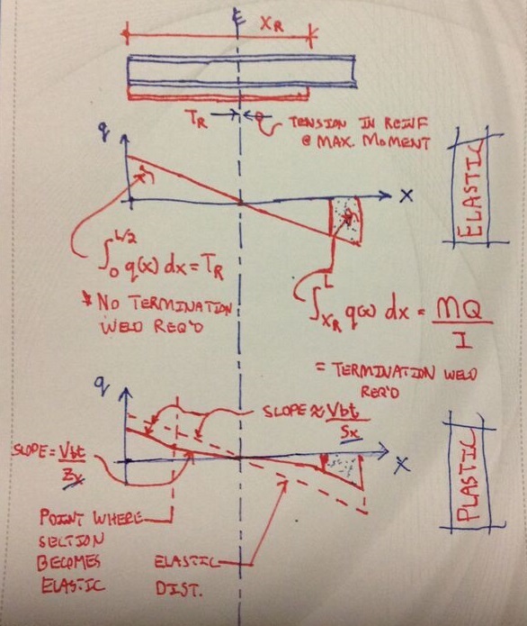
1) We design our intermittent/continuous welds to deal with the increment of moment at each location. This is the VQ/I stuff for elastic situations and the analogous formulation for plastic situations.
2) We design our intermittent welds and termination welds such that, when taken together, they are capable of developing the entire force delivered to the reinforcing at the point of maximum moment.
Additional observations:
1) When reinforcement extends the full length of the original member, termination welds are technically not required.
2) When reinforcement extends only partial length, the VQ/I welds (set out precisely and varying) will not adequately resist the entire force delivered to the reinforcing at the point of maximum moment. Additional termination welds are required to make up the deficiency. These are the MQ/I welds or the analogous formulation for plastic situations (often conservatively taken as As x Fy).
I've attempted to summarize all this graphically below.
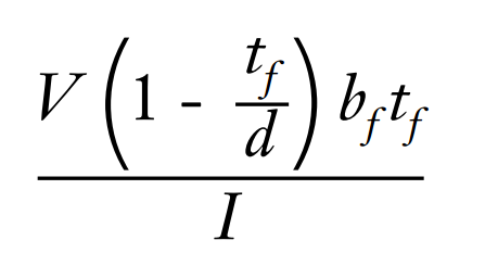
In the document that canwest supplied above, Mr. Muir presents the equation shown below for the shear flow in an elastic wide flange. I believe it to be in error and feel that the expression should be multiplied by d/2. That doesn't change any of the conclusions developed in the document however.
I like to debate structural engineering theory -- a lot. If I challenge you on something, know that I'm doing so because I respect your opinion enough to either change it or adopt it.