Tek-Tips is the largest IT community on the Internet today!

Members share and learn making Tek-Tips Forums the best source of peer-reviewed technical information on the Internet!

  • Congratulations MintJulep on being selected by the Eng-Tips community for having the most helpful posts in the forums last week. Way to Go!

Planetary Gearbox mounting 1

elinah34

Mechanical
Joined
Aug 19, 2014
Messages
162
Location
IL
Hello,

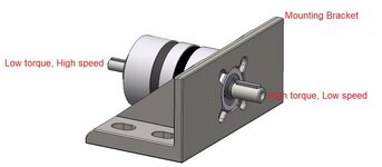
I am trying to understand why the planetary gearbox manufacturer recommends mounting his planetary gearbox through the High Torque (Low Speed) side.
I tried to figure out what is the reason, but unfortunately he didn't reply.
PLANETARY GEAR MOUNTING.JPG
A colleague told me I would better mount the gearbox through the High Torque (Low Speed) side, because otherwise "I will transfer all of the generated forces through the gearbox housing", and I am not sure I understood what he meant.

I tried to use a simplified FBD (Force Body Diagram) to analyze the reactions on the gearbox housing in both optional mounting cases (through the High or Low torque side), and it seems that in both cases the gearbox housing reaction would be the same – tangential friction forces (under the bolts' heads) that resist the same torque, no matter to which side it's connected.
Am I missing something?

Thanks!
 
This is the second time I've seen this question asked here. The gearbox low speed flange is designed to handle all of the reaction loads. It doesn't matter which side you drive it from. You need to restrain your gearbox on the low speed end. The opposite side simply isn't strong enough.

You may be able to get way with mounting from the opposite side of you aren't intending to load the gearbox to its rated values.
Good point, the only one I could understand so far.
Actually you are the one who made me wonder about this issue;):).
The first time you saw a question like this you gave another explanation :oops::
POST.JPG
 
I'm just making a quick comment based on the first post. You get a reaction at the mounting points because the housing is trying to turn in the opposite direction of the output torque. If you mount the gearbox on the output side as shown, the reaction acts as a tangential shear load on the fasteners right at the face of the gearbox. If you mount on the other side, the input side, the reaction is still there but it has to travel as a torsional load on the body of the gearbox to get to the face on the input side. A bigger consideration is whether you have an overhung load on the output shaft. Is it connected to another shaft or is it turning a pulley, sprocket or gear? If so, I would definitely try to mount to the output face.
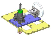
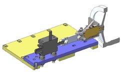
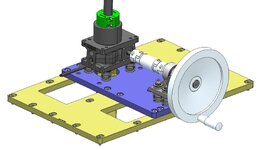
I am replying about your question what and how is connected to the gerabox:
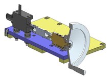
DESIGN1.JPGDESIGN2.JPGDESIGN3.JPGDESIGN4.JPG
 
Misalignment at the high speed side will experience many more cycles on the shaft coupling, high-speed shaft, bearings, and seals than the low-speed side. I would strive to provide the best alignment capability at the high speed, low torque end. The housing reaction does not seem that important to me - if the mounting screws can handle the reaction, then surely the housing is capable.
So your recommendation is to mount from the High speed/Low torque side for trying to ensure the best alignment to the "fast side"?
If so, this is opposite to what many others recommended :cry::unsure:.
 
The high torque end of the drive is the one with the highest reaction forces. Even if the housing is strong enough to absorb the reaction loads from the opposite end, more force causes more deflection and deflection reduces the contact quality and life of gearing. So the drive should last longer when mounted via the low speed end, with all other things being equal.

Reason 2: the manufacturer recommended it, which means that's what it was designed and tested to do.

So in summary, in principle I agree with your colleague but I disagree with the conclusion. The most housing load will occur when mounted on the high speed end, so mount to the low speed end.
 
Last edited:
The high torque end of the drive is the one with the highest reaction forces. Even if the housing is strong enough to absorb the reaction loads from the opposite end, more force causes more deflection and deflection reduces the contact quality and life of gearing. So the drive should last longer when mounted via the low speed end, with all other things being equal.

Reason 2: the manufacturer recommended it, which means that's what it was designed and tested to do.

So in summary, in principle I agree with your colleague but I disagree with the conclusion. The most housing load will occur when mounted on the high speed end, so mount to the low speed end.
Hey, thank you for replying.
I appreciate your statement, and maybe you are right - but it contradicts other previous claims of the same reaction torque in both cases. So without any profound explanation, FBD, external link which discusses that issue, I can't rely on it.
 
So your recommendation is to mount from the High speed/Low torque side for trying to ensure the best alignment to the "fast side"?
If so, this is opposite to what many others recommended
I would be more concerned with the induced loading due to amplified misalignment with your arrangement than with the transmitted load. What type of couplings are those, and how much misalignment capability do they have? Also, have you investigated the overhung load due to the hand wheel? Perhaps I missed it but for this mechanism it would have been helpful to include all of your sketches in your original request for assistance. Why are you doing any of this? Can you not buy a jack with a different ratio and direct-drive the input to the jack? Operators of this equipment will not like the many turns of the handle to lift/lower the load. This is an obstinate design it truly seems that there is a better way.
 
I would be more concerned with the induced loading due to amplified misalignment with your arrangement than with the transmitted load. What type of couplings are those, and how much misalignment capability do they have? Also, have you investigated the overhung load due to the hand wheel? Perhaps I missed it but for this mechanism it would have been helpful to include all of your sketches in your original request for assistance. Why are you doing any of this? Can you not buy a jack with a different ratio and direct-drive the input to the jack? Operators of this equipment will not like the many turns of the handle to lift/lower the load. This is an obstinate design it truly seems that there is a better way.
I would be happy to hear other design options, I am here for learning.
I am explaining now the reason for incorporating a planetary gearbox serially - since the gear ratio of the jack itself is very problematic (I think 1:24) for assuring a self locking of the jack (this was s safety requirement), for the specific concern you raised (a lot of manual turns, originally 100), I decided to use a planetary gearbox with 1:6 ratio and and to use it the opposite way, for increasing velocity. I checked the required torque with the wheel radius, and the operator will have to exert 3 kg for moving the wheel. This way instead of turning the wheel 100 times, they have to turn it about 20 times. As for your question about the shear force and moment on the input of the planetary gearbox - I checked it and there is a huge SOF.
 
I would be happy to hear other design options, I am here for learning.
You will get much better suggestions if you provide a better example of your complete application and the load and load guidance.
 
AIUI the casing is fixed and the input shaft drives planetary gears which drive the output shaft. The planetary gears "create" the extra toque, and balance themselves against the outer casing, so supporting the outer casing as close to where the planets are should create the lighter structure, no?

Now, increasing the speed of the shaft (post #9) ... well, that's a whole different thing ! and somewhat unrelated to how to attach this thing to the rest of the world.
 

Part and Inventory Search

Sponsor

Back
Top