Hi!
I'm doing a marine engineering project about 30x30m offshore platform on steel tube piles. The structure need to withstand lateral forces mainly from berthing ship (wind loads) and vertical forces. So as it's 3D structure I created 3D model in Robot structural analyses. I'm going to use both vertical and 1/3 diagonal piles. Most of the horizontal forces would be taken by diagonal piles.
Data that i have in hand about the layered soil includes Young’s Modulus E, cohesiveness c, unit weight γ, porosity, andgle of internal friction φ. So no STP results.
I've tried to find solutions to calculate spring supports for piled foundation and found program called REX piles demo version as robot "Add-in". I think i got quite interesting and reasonable results using it. So i took these results as basis and started to find ways to calculate spring supports by hand to get comparative results.
For lateral supports there are multiple elastic spings solutions for different soils, conditions etc (and of course there are may others):
For example this source Table 1
I used probably quite conservative Vesic's (1961) solution.
And of course classical p-y curve.
And much less conservative solution (fig. 3.1)
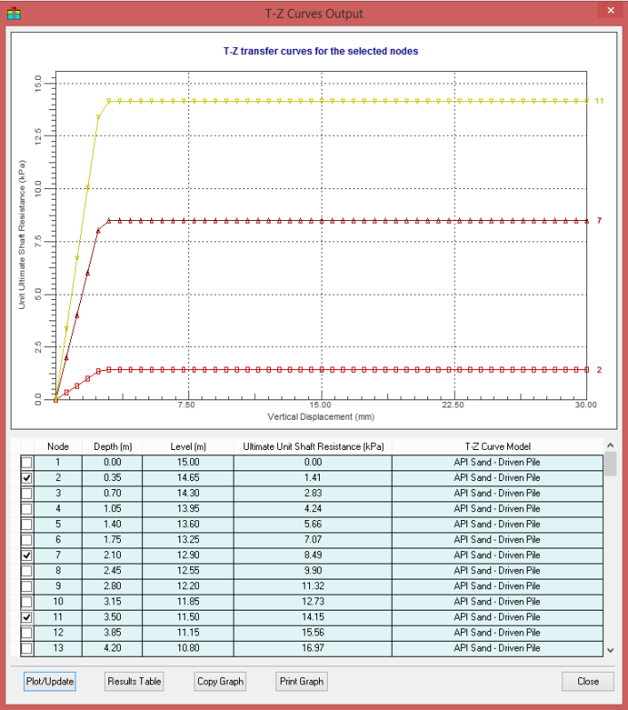
Then it comes more difficult part for me. It's the vertical springs that would represent frictional conditions. I've read Tomlinson (and many other) books, googled researchis but haven't found great enough calculations.
Have anyone faced similar problems or just can give some ideas where to look for the solutions?
Cheers
I'm doing a marine engineering project about 30x30m offshore platform on steel tube piles. The structure need to withstand lateral forces mainly from berthing ship (wind loads) and vertical forces. So as it's 3D structure I created 3D model in Robot structural analyses. I'm going to use both vertical and 1/3 diagonal piles. Most of the horizontal forces would be taken by diagonal piles.
Data that i have in hand about the layered soil includes Young’s Modulus E, cohesiveness c, unit weight γ, porosity, andgle of internal friction φ. So no STP results.
I've tried to find solutions to calculate spring supports for piled foundation and found program called REX piles demo version as robot "Add-in". I think i got quite interesting and reasonable results using it. So i took these results as basis and started to find ways to calculate spring supports by hand to get comparative results.
For lateral supports there are multiple elastic spings solutions for different soils, conditions etc (and of course there are may others):
For example this source Table 1
I used probably quite conservative Vesic's (1961) solution.
And of course classical p-y curve.
And much less conservative solution (fig. 3.1)
Then it comes more difficult part for me. It's the vertical springs that would represent frictional conditions. I've read Tomlinson (and many other) books, googled researchis but haven't found great enough calculations.
Have anyone faced similar problems or just can give some ideas where to look for the solutions?
Cheers