Continue to Site

Eng-Tips is the largest engineering community on the Internet

Intelligent Work Forums for Engineering Professionals

  • Congratulations IRstuff on being selected by the Eng-Tips community for having the most helpful posts in the forums last week. Way to Go!

Perpendicular Beam to Brace Against Web Crippling 1

Status
Not open for further replies.

RFreund

Structural
Aug 14, 2010
1,885
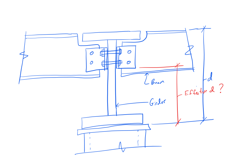
When a beam frames over the top of a column, web crippling is typically checked. In the situation where a girder frames over the top of the column and beams frame into the side of the girder, can the beam to girder connection be considered to "brace" against web crippling or to reduce the effective height "h" of the girder?

Web_Crippling_-_Effective_Depth_nsxpqj.png


EIT
 
Replies continue below

Recommended for you

No; web crippling is a bearing problem. Bearing stiffeners would be required if the girder is not adequate on its own.

BA
 
We usually use vertical stiffener plates on each side of the girder and then extend them a bit to also serve as single plate beam connectors.

Check out Eng-Tips Forum's Policies here:
faq731-376
 
It appears from the sketch that the column is an HSS, so stiffener plates may be required each side of the girder over each wall of the HSS.

Alternatively, a single plate stiffener could be considered each side of the girder as suggested by JAE, perhaps with a thicker cap plate over the column.


BA
 
Thanks for the suggestions. I drew what looks like an HSS but the actual condition is concrete. This is an existing condition. I am trying to to see if the angle help contribute at to the web strength or reduce it's effective length. Web crippling is interesting in that it is similar to buckling and the equation is proportional to "d" but it appears that the buckling mostly occurs in the lower portion of the web. Only a half height stiffener is required but I would assume that the stiffener would need to start at the bottom. Which would be a tough repair if the angles extend the full (almost full) height of the beam web.

Thanks again!

EIT
 
If the column is concrete, and presumably the girder bears on a steel plate, I would be surprised if web crippling is an issue because the length of bearing is substantial. Web crippling, as I understand it, is not proportional to 'd'. What equation are you using?

Whether or not web crippling is an issue, it is good practice to provide a stiffener in the girder to provide racking stability.

BA
 
Coincidentally I was just checking this limit state myself one one of my projects.

Anybody have an idea on why the limit state is a function of "d" if the crippling occurs only locally (beneath the load - not across the entire "d" ).

Also what I don't understand is why tf is in the equation at all?
 
As RFreund noted, web crippling is a local phenomenon in which plastic hinges form in the flanges (hence tf in the equation) along with yield lines in the web at the point of bearing. Since the failure occurs at the point of bearing, AISC requires that stiffeners or doubler plates used to reinforce against crippling need only extend half the depth of the beam. The derivation of the web crippling equation in AISC can be found here: Link.
 
JAE... that's what I do, generally.

Looks after web crippling and maintaining the section for post elastic deformation... and a multitude of other sins...

Dik
 
My take:

1) Analytically, you're dealing buckling on a yield line mechanism like that shown below per Deker.

2) For plate girders, the 2 x alpha dimension is 50 tw. That's pretty tall. I don't know if that holds exactly for non-plate girders but the take away, I think, is that you're looking at buckling over a substantial depth. Probably almost the entire beam depth in a lot of cases.

3) Anything that interrupts the buckling mechanism shown below is going to help some. Anything.

4) I don't know that it is necessary to start the stiffener reinforcing from the very bottom of the web. The purpose of the stiffener, for this one failure mode, is not load delivery but, rather, out of plane web bracing. A stiffener doesn't necessarily need to bottom out to get that done in my opinion.

5) In my opinion, a pair of angles tightly bolted and spanning most of the beam depth almost certainly disrupts the buckling pattern that is web crippling. Of course, to make that argument, you have to go off reservation a bit which requires some risk tolerance and a willingness to expend effort that may not be commensurate with your fee.

6) One alternate reinforcing scheme that would involve less head scratching would be to place half height vertical stiffeners either side of the secondary beams. I don't know your exact proportions but I have a hard time envisioning a practical arrangement for which that would not work.

7) A second alternate reinforcing scheme, space permitting, would involve the use of longitudinal stiffeners to disrupt the presumed buckling pattern. Some googling will turn up some papers on that. Medium head scratching.

c01_bpa6bq.jpg


I like to debate structural engineering theory -- a lot. If I challenge you on something, know that I'm doing so because I respect your opinion enough to either change it or adopt it.
 
@BA here is the AISC equation for Web Crippling (which includes d (depth of girder):
Web_Crippling_-_AISC_Eqn_loj8pj.png

Web_Crippling_-_AISC_Eqn_2_nxzknz.png


Interesting to note that the 2016 Manual states that the stiffener must be 3/4 depth whereas the 2010 only required half-depth.

@Deker: Thanks for the reference.

@KootK: In general I agree with your input, a few questions comments:

2.) I question this. Although the equations seem to indicate that the entire height is involved in the capacity, according to the AISC commentary the buckling only occurs in a portion of the web directly adjacent to the loaded edge. So part of me says "the height should not affect web crippling based on what my eyes see", but the other part of me says "this is probably a higher mode of buckling which is still dependent on the total height".

3.) Agreed

4.) Same response as item #2). "By inspection" I want it directly attached to the loaded flange, "mathematically" I could see that it should matter.

5.) Agreed, just not sure how to put numbers to this.

6.) Also Agreed

7.) I'm a little leery of this one as well due to my comments in item #1.

Here is the commentary:
Web_Crippling_-_AISC_Commentary_h7xrie.png


EIT
 
Thanks for the failure mode picture KootK. I understand web crippling much better now!

Looking at that makes me question why bf isn't included in the equation. And I still don't understand why d is in the equation. Except to possibly be used as an upper-bound on the two alpha parameter, it doesn't seem to come in to play at all.
 
You're very welcome cal91.

cal91 said:
Looking at that makes me question why bf isn't included in the equation.

Interesting point. Maybe it's only a part of the flange near the web that really participates so more based on tf/tw ratio? Just guessing/intuiting.

RFreund said:
I question this. Although the equations seem to indicate that the entire height is involved in the capacity, according to the AISC commentary the buckling only occurs in a portion of the web directly adjacent to the loaded edge.

I question it too, really, despite having seen it in print.

cal91 said:
And I still don't understand why d is in the equation.

Although the lion's share of the lateral displacement happens near the loaded flange, I think that the level of rotation restraint provided to the other end of the buckling web segment is still very much a function of the entire web depths. That's my speculation at least. I think that would jive with depth being and inverse linear parameter.

I like to debate structural engineering theory -- a lot. If I challenge you on something, know that I'm doing so because I respect your opinion enough to either change it or adopt it.
 
There is a lot of good information in Chapter 2 of the AISC Manual. If this is an overframed condition (Gerber syster or drop-in beam system), you need to make sure to check web sidesway buckling. Would provide a pair of full depth stiffeners over the column at the overframed beam.
 
@RFreund thanks for your post. I don't completely get it at the moment, but it appears that my understanding of web crippling is not current.

BA
 
KootK said:
7) A second alternate reinforcing scheme, space permitting, would involve the use of longitudinal stiffeners to disrupt the presumed buckling pattern. Some googling will turn up some papers on that. Medium head scratching.

I also would have thought this would increase the crippling capacity, but I just read this which seems to suggest otherwise:

Guide to Stability Design Criteria for Metal Structures (6th Ed.) said:
When a longitudinal stiffener is provided to increase the capacity of the web under in-plane bending, the stiffener is usually placed at a distance equal to 0.2 to 0.25 times the web depth from the compression flange. The effect of the presence of such a stiffener on the behavior of the web under in-plane compressive edge loads was investigated by Elgaaly and Salkar (1992), Shimizu et al. (1991), Bergfelt (1983), and Kutmanova et al. (1991). A general conclusion made from these studies is that the effect of such a stiffener on the ultimate capacity of the web, under in-plane compressive edge loading, is generally negligable. This is different from the conclusion reached by Rockey based on his theoretical studies on the effect of the longitudinal stiffener on the elastic web buckling under compressive edge loading, which was discussed earlier in this chapter.

Would you mind sharing the source of Fig. 1 that you posted above? I'd like to see if it would be worth getting as a reference.
 
A very similar version of the image KootK shared is in "Design of Steel Structures" (third edition) by Gaylord, Gaylord, and Stallmeyer. The textbook references a paper by T.M. Roberts ("Slender Plate Girders Subjected to Edge Loading") from the September 1981 issue of Proceedings of the Institution of Civil Engineers. The web local crippling equations in the AISC Specification (Equations J10-4, J10-5a, and J10-5b from AISC 360-10) appear to be based on the Roberts research.


Deker said:
Would you mind sharing the source of Fig. 1 that you posted above?

Of course. These be my sources. There are derivations of the crippling math in there.

Link
Link

OP said:
I also would have thought this would increase the crippling capacity, but I just read this which seems to suggest otherwise

Interesting. What I take from that is that the 0.20 - 0.25 high longitudinal stiffeners commonly provided to address shear buckling and flexural compression web buckling don't extend low enough to do much about crippling. So, again, it all comes back to how tall that buckled chunk of web is. The photo below is from the Rockey paper. Looking at that, I'd have a pretty tough time accepting that suitably located longitudinal stiffeners wouldn't help. As shown in the picture, they would reduce the height of the buckling. I'd think that capacity would go up in proportion to the squared inverse of that reduction.

Practically, of one need to span the longitudinal stiffeners between two vertical stiffeners, then using the two vertical stiffeners alone would seem the logical choice.

c01_ukbie3.jpg


I like to debate structural engineering theory -- a lot. If I challenge you on something, know that I'm doing so because I respect your opinion enough to either change it or adopt it.
 
Hokie93 - Thanks for the reference. I wasn't able to track down a free version of the Roberts paper, but he did author the chapter of the book I linked to above which contained the web crippling derivations.

KootK - Great references, thanks for sharing. The longitudinal stiffeners in the Elgaaly and Salkar tests actually were placed near the top flange (loaded flange) at distance of 0.2d, while the crippling occurred within a height of 0.16d. But your point stands, and I agree that a well-placed longitudinal stiffener (25tw from the loaded flange?) would have to increase the crippling capacity. Also agree that for OP's condition the two vertical stiffeners alone seem the most practical. I thought this bit from your second reference was interesting on how bf was removed and d was inserted into the crippling equations:

Untitled_eyed6t.png
 
Status
Not open for further replies.

Part and Inventory Search

Sponsor