Continue to Site

Eng-Tips is the largest engineering community on the Internet

Intelligent Work Forums for Engineering Professionals

  • Congratulations Ron247 on being selected by the Eng-Tips community for having the most helpful posts in the forums last week. Way to Go!

NX 8.5 drafting 1

Status
Not open for further replies.

aleksandar81

Mechanical
Jul 2, 2014
137
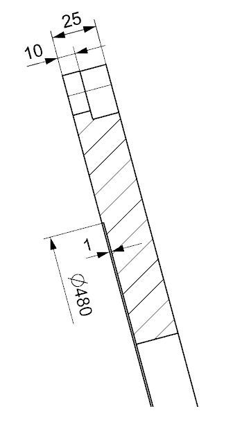
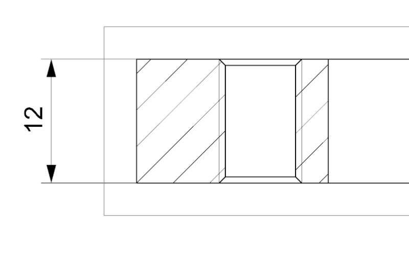
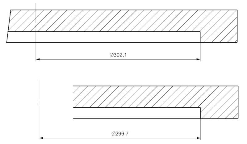
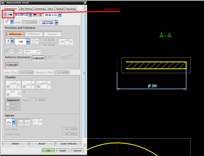
It's possible to dimension diameter on section D480 (pic1), and thread (pic2) without using fake dimension. My thread symbol is constantly on the projection full circle, even when in customer defaults I change to 3/4 circle.

1_atsmjd.jpg


2_r3oxez.png
 
Replies continue below

Recommended for you

For the first issue, if you can include either a 2D or 3D Centerline in that view, you can select it and the dimension should double if you're using a Cylindrical dimension. You may have to enlarge your view boundary and/or make the 2D/3D Centerline view dependent (expand the view then insert 2D/3D Centerline, expand out of the view, create dimension, fix view boundary).

Not sure what your question is with the second issue. Are you trying to change the display of the threads? If so, that may be a part specific setting meaning only new parts will be affected by changing the customer defaults. You'll have to change that via the View Style/Settings dialog. Do not forget for a change in customer defaults to take effect, you must restart NX for it to take effect. If you're using a template, changing the customer defaults won't have an effect on the template file.

Tim Flater
NX Designer
NX 9.0.3.4 Win7 Pro x64 SP1
Intel Xeon 2.53 GHz 6GB RAM
NVIDIA Quadro 4000 2GB
 
Thank you,my second question is how in section I can dimension thread.I only see this option as hole callout in radial dialog for threads in view.Here is for NX 9,same is for NX8.5.

12_fzf5ju.png


What I want is this

threaddim3_oopcz8.gif
 
There's a 'Hole Callout' option available with liner (Horizontal or Vertical) dimensions as well.

John R. Baker, P.E.
EX-Product 'Evangelist'
Irvine, CA
Siemens PLM:
UG/NX Museum:

The secret of life is not finding someone to live with
It's finding someone you can't live without
 
Thank you John!


@Xwheelguy

Cylindrical dimension can't do this, it gives only dimension value between two points.
 
Cylindrical dimension can't do this, it gives only dimension value between two points

I beg to differ... it has always worked for me as long as the centerline is picked first and the edge of the cylinder second.

"Know the rules well, so you can break them effectively."
-Dalai Lama XIV
 
@ewh


I tried that and it did work, except when the centerline is outside of section boundary.D302,1 is the true diametar.Thank you all very much.[cheers]

Untitled_qrmkm1.png
 
There may be other issues involved, as I am able to get true diameter dimensions using a centerline within the same view and the edge as well as using centerlines from other views (as long as it represents the same axis and orientation).

"Know the rules well, so you can break them effectively."
-Dalai Lama XIV
 
I guess, I will have to stick with the centerline within the boundary. There could be the issue with my NX since D296,7 doesn't have any sense.
 
First You have to create centerline of hole. Use 3D centerline which will automatic place in center of hole. Then You have to choose cylindrical dimension. Next select centreline and second edge of hole. You should receive something like on Your last picture, first section. Then select this dimension, right click style, go to dimension tab and deselect left | and lest arrow. You should get diameter like on first picture in this thread.

pic_ij9ibi.png


With best regards
Michael
 
The Centerline can be View Dependent if you do not wish to see it. The View Boundary can be set to manual and you can hide it after placing the dimension.

Tim Flater
NX Designer
NX 9.0.3.4 Win7 Pro x64 SP1
Intel Xeon 2.53 GHz 6GB RAM
NVIDIA Quadro 4000 2GB
 
Here's a video if anyone wants to see what I mean by making the Centerline View Dependent and adjusting the View Boundary.

centerline.zip

Tim Flater
NX Designer
NX 9.0.3.4 Win7 Pro x64 SP1
Intel Xeon 2.53 GHz 6GB RAM
NVIDIA Quadro 4000 2GB
 
Or you can just create and name the centerline in modeling under properties
and then you can reference it in drafting as your first pick without
going in and out of view dependent edit.
 
Here's a word document on how to dimension using a named centerline.
This is for NX8.5 and earlier. From NX9 and beyond it's a totally
different process using a "name selection" box and a few other different things of course.
 
 http://files.engineering.com/getfile.aspx?folder=f1c48590-e7a9-4058-9997-bd596f6137b3&file=diameter_dimensioning.docx
Status
Not open for further replies.

Part and Inventory Search

Sponsor