Continue to Site

Eng-Tips is the largest engineering community on the Internet

Intelligent Work Forums for Engineering Professionals

  • Congratulations waross on being selected by the Eng-Tips community for having the most helpful posts in the forums last week. Way to Go!

New steel beam supports beside existing p.t. bea,s 2

Status
Not open for further replies.

ajk1

Structural
Apr 22, 2011
1,791
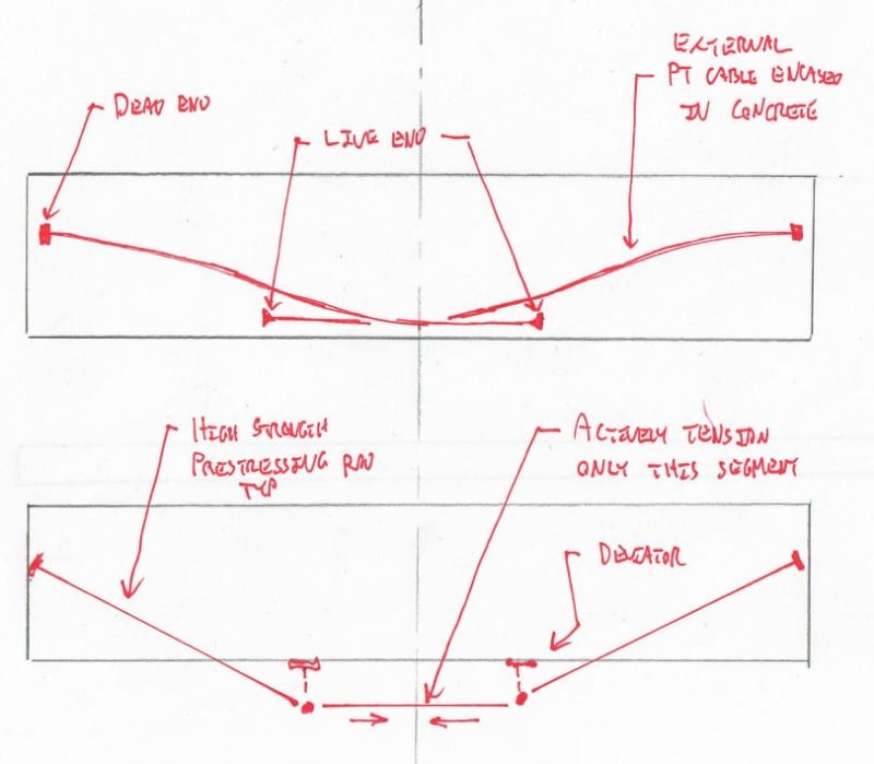
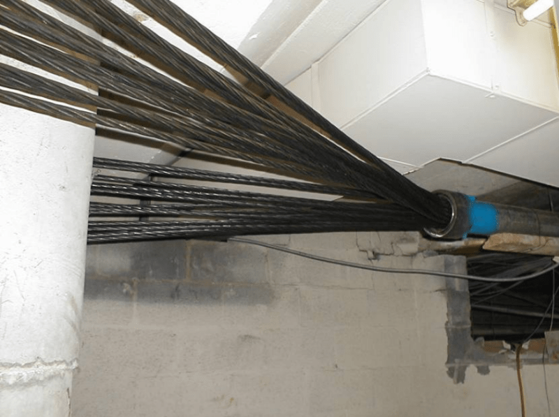
In an exiting parking garage with post-tensioned (unbonded)tendons, it is desired to put new steel beams beside each existing p.t. concrete beam so that if all of the tendons fail the steel beams can take the load.
in a p.t. beam,
Question

Is it satisfactory to place the new steel beams on one side only of each existing conc beam? I am concerned that the existing bottom rebar in the slab will not be continuous between the new steel beams. Please see the attached sketch. Do you agree with this concern? If so, could place new steel beams each side of each existing p.t. conc beam, but this would double the on-site labour to install the beams, as well as a greater total weight of new steel.
 
 https://files.engineering.com/getfile.aspx?folder=aab93262-4371-478a-935a-ae9156272b06&file=propsed_steel_bams.pdf
Replies continue below

Recommended for you

ajk1 said:
...I think external p.t. is probably the most practical and perhaps the most economical...

I agree (and we discussed external PT at length here: thread507-445231), however, given that your existing beam section does not meet CSA code for min. bonded reinforcing steel at the bottom (2#5), your new strengthening system should address this and consider bringing it up to code, in my opinion. Your Building Department may be able to give you an opinion if you are required to do so, given that this may be 'grandfathered' from previous building codes. If they deem it is required then external UNbonded PT won't help you.

You may consider adding new external BONDED PT tendons on each side of the beam web and encasing/jacketing in concrete. Unfortunately, such concrete encasement adds considerable mass (and work effort and therefore time and cost) and may have implication to other structural elements (column, girders, footings), and sort of takes away from the 'simplicity' of external PT strengthening. It does, however, solve fire-rating issues, and also your 'bird poop' issues too.


to Ingenuity: Thanks for pointing this out about minimum bonded steel requirements.
As to columns & footing: The structure was designed for future vertical addition, which has since been decided by the owner will not be built, and other things have been done in the intervening years that were based on no future addition. So the columns and footings have extra capacity, and should not be a problem if some extra load is added. However it would be preferable not to have to add concrete if possible, so I will have to look into the minimum bonded steel issue. As to fireproofing, I would expect that can be done with spray fireproofing, and that can be shaped to slope back to the beam so that birds will not sit on the external p.t.
 
I am not sure if CSA A23.3 Table 18.1 has changed from 2004 when the following was the requirement for min. bonded reinforcement:

CaptureCSA_UNBONDED_ymo3tf.png


Min. bonded reinforcement to UNbonded PT beams to ACI 318 dates back to 1971 - less than 10 years after prestressed concrete design was first codified/introduced to ACI 318 in 1963. As min = 0.004A remains the same value used today.

Somewhat interestingly, ACI 318 did NOT introduce min. reinforcement requirements for reinfroced concrete flexural elments, based explicitly on cracking moment, until 1995.
 
To Ingenuity - There is no change to the minimum beam reinf for beams in the latest CSA A23.3 edition i.e. the year 2014 edition. I will see if I can find the 1977 code requirements of CSA A23.3

Can anyone comment on what the total load deflection limit should be? Please see earlier comment in this string. The drains are midspan between beams, so they probably are not too affected by deflection (if all the beams deflect about the same amount due to tendon breakage (which may not be the case, but anyway let's assume they do...).
 
I'd start with what you can tolerate with respect to cracking at the top of the existing beams and work backwards from there. I'd expect that to produce much tighter deflection limits than you've proposed.
 
To Kootk-an interesting thought. I will look into it. Thank you.
 
To Ingenuity: I see now that the beams with 2#5 or 2#6 bottom bars have bonded tendons. The beams with unbonded tendons have much greater bottom steel. I am working from home and not so easy at my age, viewing the drawings on my laptop, or I would likely have seen this earlier. Incidentally, I have the 1973 edition of CSA A23,3, and the minimum amount of bottom steel for beams with unbonded tendons was the greater of 0.004A and Nc/0.5fy where Nc = tensile force in the concrete under load of D + 1.2L. So it looks like there should be no issue with insufficient existing bottom steel with the proposed new external p.t. Sorry that I did not notice that the small amount of bottom steel was only in the beams with bonded tendons.
 
Some beams have bonded tendons and some have unbonded tendons? Does that mean that the area with bonded tendons is okay without remedial measures?

BA
 
I know that one of your concerns is having to stress the tendons within adjacent, interior space. I did some noodling in the sketches below trying to devise a scheme that would allow you to do the stressing away from the ends of the beams. I've not done this myself so I'll need to rely on other, more knowledgeable folks to comment on whether such concepts are impractical. Obviously, fire rating concerns need to be addressed one way or another. I believe that you can get intumescent coated threadbar for bridge applications but I'm sure that's wildly expensive.

c01_vrb0ky.jpg
 
BAretired said:
Does that mean that the area with bonded tendons is okay without remedial measures?

Assuming that the grouting was done correctly...big "IF" depending on who did it, type of pump equipment used, and what grout they used. The 70's for grouted PT construction (in North America for buildings) was not always undertaken by specialized PT subs with grouting expertise.
 
KootK,

In the first sketch, if you want the biggest bang for your buck so far as deflection is concerned, place all new tendons straight along the bottom and move the live ends as close as possible to the end of the beam so that you get double the number of tendons for most of the beam length.

However, if all of the existing tendons fail, I would be concerned about the beam shortening and pulling away from the girder, causing a potential shear failure.

Personally, I would use a steel truss each side of each existing beam. The top chord could be a single angle which could bolt directly to the beam, perhaps using through bolts. The bottom chord, if it ended up below the existing beam, could be a symmetrical section. For fire proofing, pneumatically placed concrete (gunite) could be used.

BA
 
If holes could be drilled through the existing girders, the ideal solution would be to thread tendons through the girders. Then, harped grouted strands could be used which would provide negative moment resistance at girders.

BA
 
KootK said:
I've not done this myself so I'll need to rely on other, more knowledgeable folks to comment on whether such concepts are impractical.

Experienced design-build PT subs often 'engineer' some creative solutions where access for end-stressing is problematic:


Here is one from Washington, DC - 30 x 0.5" dia multistrand tendon wrapped around a circular column, as a fixed-end anchorage:

CaptureEXPT1_wifb3x.png


Bent steel plate used as a wearing/bearing/friction surface:

CaptureEXPT2_lttvsn.png


A project from California, with a solution for center-stressing - using an anchorage tube - with barrel chucks, and overlapping tendons:

CaptureEXPT3_wme614.png
 
ajk1: I am pleased to read that the sections likely meet the min. steel requirements.

ajk1 said:
1973 edition of CSA A23,3, and the minimum amount of bottom steel for beams with unbonded tendons was the greater of 0.004A and Nc/0.5fy where Nc = tensile force in the concrete under load of D + 1.2L.

Identical to (and copy of) ACI 318-71 §18.9.2:

Captureaci318-71_jkhi9k.png
 
Personally, I would use a steel truss each side of each existing beam. The top chord could be a single angle which could bolt directly to the beam, perhaps using through bolts. The bottom chord, if it ended up below the existing beam, could be a symmetrical section. For fire proofing, pneumatically placed concrete (gunite) could be used.

An very interesting idea! Thanks.
 
Can someone tell me how the "quote feature"on this system works? It looks neat, but I don't knows how to use it. I tried clicking on the quote icon and typing the person's name, and it displays the person's name properly, but then I do not know how to type in my response so that it appears as it does when I see responses to me.
 
@Ingenuity. Neat stuff, thanks. I never would have thought to yank on a column like that but I guess she's huge and pulling into a solid beam.

I originally tried to do my sketches to scale and was struck by how slender a 54' x 2' beam really is at L/h = 27. It may well be that prestressing was / is the only practical way to go about it without adding significant depth.
 
. Personally, I would use a steel truss each side of each existing beam. The top chord could be a single angle which could bolt directly to the beam, perhaps using through bolts. The bottom chord, if it ended up below the existing beam, could be a symmetrical section. For fire proofing, pneumatically placed concrete (gunite) could be used.
BA

Yes I think so.
AJK1
 
Sorry, I meant attribute this to BARetired, rather than to Kootk. I still have not figured out how to use the "quote" feature on this system! If anyone could tell me, I would be greatful.

To BARetired: You say that "If holes could be drilled through the existing girders, the ideal solution would be to thread tendons through the girders. Then, harped grouted strands could be used which would provide negative moment resistance at girders."

I do not understand. Do you mean if holes could be drilled longitudinally thru the girder? How would you drill a hole to match the curvature of a harped tendon?
 
For the steel beam and steel truss options, enclosing with fire-rated drywall for wet conditions may be an alternative to spray fireproofing. Would look better, and be a better solution to birds alighting, but would be subject to vandalism and impact damage, but so is spray fireproofing and the spray fireproofing we did there in 2013 has stood up reasonably well to-date.

There is I believe a company that advertises that they do urethane injection of tendons. Has anyone experience with that? My feeling is that they would not be able to prevent ongoing wire failures, but has anyone experience with it, or heard anything good or bad about it?

to Kootk - how do you anchor the tendons to the sides of the beams? Do you drill thru the beam to do that (there are stirrups there; also some beams flare out at their end few feet)? Also there are the internal existing tendons here, where the new exterior tendons would be anchored. In addition to the anchorage question, I think that I share BARetired's concerns about pulling the beam away from the supporting girder, so somehow calculations would be required to check for that.
 
Status
Not open for further replies.

Part and Inventory Search

Sponsor