Tek-Tips is the largest IT community on the Internet today!

Members share and learn making Tek-Tips Forums the best source of peer-reviewed technical information on the Internet!

  • Congratulations cowski on being selected by the Eng-Tips community for having the most helpful posts in the forums last week. Way to Go!

Multple single segment position

Wuzhee

Automotive
Joined
Jul 12, 2022
Messages
298
Location
DE
Hello there!
I've got a ball here for discussion. The ball is constrained between seating elements and is rotated around Datum A by the slot on top.
My coworker made the decision to give that slot two different position tolerances.
His idea: 0.08 concentricity to A because the offset isn't that important here.
0.05 to B because the right angle is more important in the ball function.

I have objected his proposal because in my understanding, this callout on 2+0,05 applies as the following:
Top row means concentricity to A.
Bot row means perpendicularity to B.
0.05 < 0.08 hence the top row is meaningless.
BALL 1.jpg

His explanation:
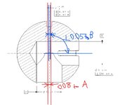
Top row applies in the upper view as discussed. Bot row applies in top view like this:
Important note: This view is NOT PRESENT on the drawing, I have made it to explain this visually.
BALL 2.jpg

What is the correct interpretation of the multiple segment callout?
Who's in the wrong here?
 

Attachments

  • BALL 1.jpg
    BALL 1.jpg
    161.2 KB · Views: 0
Why do so many users choose a smaller text size for the tolerance? All text on a drawing should be a uniform size.

As to the requirement, since there is allowable variation between datum feature A and datum feature B the two tolerance zones are not necessarily aligned and therefor the two tolerances are not directly comparable.

Also, they control two different things. One is how "centered" the slot location is on datum feature A and the second one controls orientation of the slot relative to datum feature B. These are independent controls and leaving either off leaves the feature with undefined variation.
 
Why do so many users choose a smaller text size for the tolerance? All text on a drawing should be a uniform size.
Company standard, also it is locked in the Catia dwg standard file. I can not change that and I'm not going the extra mile to manually change them all the time.

Also, they control two different things.
So to say, both controls are correct. Because B is also an axis, having the 90° BSC angle to B controls the orientaion.
But if I'm nitpicking a bit, can the 0.05 perpendicularity (marked blue on top image) "wander", (translate/expand, by the Y14.5 def.) inside the 0.08 position?
 
Someone set the company standard. When I say "users" I mean whoever it is who makes that poor choice. If I meant "you" I would have written that. One might note that Y14.2 doesn't mention different sizes and the dimensioning and tolerancing standard also doesn't use different sizes. Why would one do this? If there is a note and someone wants to add a stacked +/- tolerance and doesn't want to erase all the note text above it and redo that. Unless you are working on paper or Mylar, there is no reason at all.

Since the main thing the reference to datum feature B controls is perpendicularity, it would be more clear to just use perpendicularity.

Maybe I should make the text height proportional to the length of the word? For improved readability.
 
Regarding the slot, if the concern is accurate orientation relative to datum B and a loose location control relative to A, it could be a better idea to apply a composite position tolerance relative to B primary and A secondary and refine it to B in the second segment. But if that is to be implemented, the qualification of one datum feature relative to the other should also be reversed. Regardless, currently the location of datum feature B is uncontrolled. Theoretically, it may even not intersect at all with the other hole and that would not be noticed by inspecting to that drawing.
 
So odd to make that claim when the documentation says different:

1751644113970.png

See also: http://catiadoc.free.fr/online/cfyugdr_C2/cfyugdrsa0407.htm

Also, it's not "located" to B. It can only possibly be oriented to B much the same way a primary reference to a plane orients a hole, so a composite tolerance is an even worse idea, but since this is a single feature it cannot have a pattern refinement.
 

Part and Inventory Search

Sponsor

Back
Top