Continue to Site

Eng-Tips is the largest engineering community on the Internet

Intelligent Work Forums for Engineering Professionals

  • Congratulations KootK on being selected by the Eng-Tips community for having the most helpful posts in the forums last week. Way to Go!

modeling small steel canopy roof

Status
Not open for further replies.

mats12

Geotechnical
Dec 17, 2016
181
Its a small structure but I want to model it correctly. Im looking for some good advice.

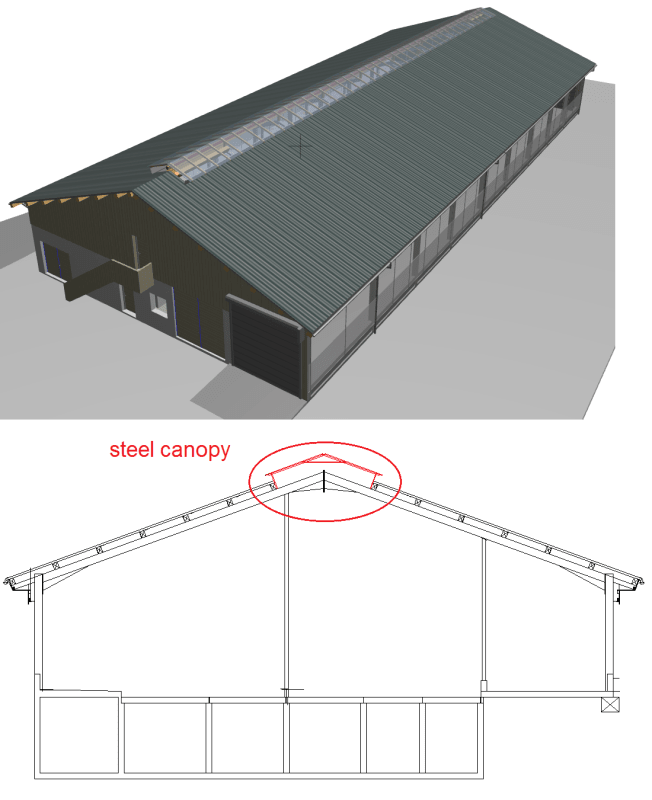
I have to design a small steel canopy roof on top of a steel barn with light polycarbonate roof plates on top of it.

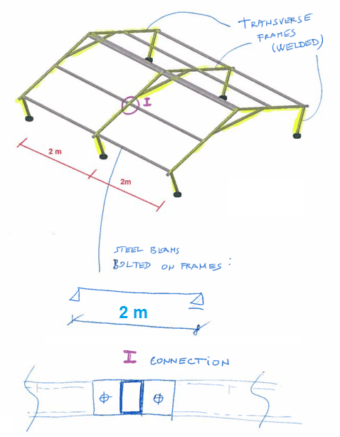
This canopy is made of transverse steel frames (all elements welded together) and longit. steel beams that are bolted between steel frames.

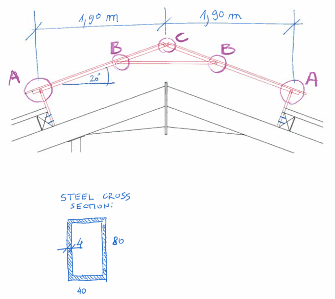
All sections are hollow: 80 x 40 x 4 mm

Would you consider connections between elements of welded transverse frames as moment connections or as pinned?
(If i use pinned connections I get much larger moments and deflections in my frame)

Critical is the connection between a steel column and beam (connection A). I think I should use some additional reinf. steel plates there to make it more stiff/rigid. What do you suggest?

Im also wondering what would you do about horizontal stability of this conopy. Making X bracing in a roof plane or something similar seems overkill.


02_gqcvgp.png


04_hxoxzy.png


000_euwhho.png
 
Replies continue below

Recommended for you

A,B & C likely best just welded. Takes minimal effort also. I looks good.
 
Connections at A, B and C should be considered pinned unless special provisions can be made to resist moment.

To stiffen the canopy, the simplest method is to fix the base of the columns to the main frame. At that location, a moment connection is more easily managed using a base plate bolted or welded to the main member.

Alternatively, some stiffness could be gained by dropping the horizontal member at 'B' down and connecting to the apex of the main frame.

BA
 
I don't know BA, I think "C" could probably be made fixed fairly easily (size a PJP or CJP all around). Agree that "B" should be pinned, and that "A" will need to be detailed specifically with moment resistance in mind if not considered pinned.


----
The name is a long story -- just call me Lo.
 
Yes Lo, I think you are correct; but I suspect making the members continuous at joint 'C' would have little effect in reducing moments elsewhere.

BA
 
The OP says that all joints will be welded tube to tube, so I don't see any reason not to assume all joints as fixed.
 
gte447f said:
The OP says that all joints will be welded tube to tube, so I don't see any reason not to assume all joints as fixed.

There is a very good reason. If two HSS members meet at 90o, two walls of one HSS has nothing to push or pull against other than the thin shell of the other HSS.

Another point is that if the members have the same width as they do here, the weld occurs at the radius of both shapes. That is a special weld requiring a written and approved procedure. It is not ideal for transferring tension or compression.

BA
 
BA, fair point about the flexibility of the tube wall to out of plane point loads. If you designed/checked the wall of the HSS per the AISC specs for point loads on HSS, then would you be OK with considering it fixed.

On your second point about welding at the radiused corner, well it is what it is... the OP said they are going to be all welded connections.

Looking back at your original response to the OP, I think your advice there is spot on, in that it would be conservative for deflections to assume all joints pinned except fixed at the base of the columns. My question for you is would you fully weld the joints (A, B and C) and just consider them pinned for design, or would you detail some other type of pinned connection other than a fully welded tube to tube connection?
 
It is normal practice to use fillet welds around web members of a truss when all members are HSS. So I would weld all around, recognize that some moment is developed but treat them as pinned joints unless specially detailed to resist moment. In the case of Joint C, it would be okay to weld the two members together and treat them pretty much as continuous. If in doubt, a stiffener plate could be added at the end of one member.

I recall an instance a few years ago where the EOR had designed a very substantial HSS truss as fully continuous. I don't remember the size of the members offhand but they were something like HSS 10 x 12 x 1/2". Web members were narrower than the chords so that welding on the radiused corners was avoided. Specifications called for all welded connections to develop the full strength of each member. I mentioned to my client, the fabricator, that this was an unreasonable demand requiring chord members to be cut open at every panel point in order to insert stiffener plates, then butt welded together and ground smooth because the truss was exposed to view and the architect did not want visible reinforcing outside the members. The EOR was not prepared to provide design moments at each connection or in any way to relax the specification, so the truss was fabricated as described above...totally ridiculous.

BA
 
Mats12:
I would make the two legs (from ‘A’ to the primary structure rafters) individual pieces and able to take some moment and shear at their base detail on the primary structure. They should be designed to take the gravity loads and any lateral loads from the small monitor or skylight (not really a canopy in my book) roof system above. They should have a saddle at their tops which will accept the eave HSS members which run the length of the bldg., btwn. the legs, or over them in several continuous spans over a number of legs. This same saddle detail should accept the reaction points from the small roof trusses, about 12.5’ long, from above. The roof truss would have a bot. chord from ‘A’ to ‘A’, and two top chords from ‘A to B to C’. It might also have a king post and a couple diags., from the bot. of the king post to the mid length of the rafter members. These parts can all be fabed. (cut, jigged, fixtured and welded) as fairly small individual pieces, and they should be installed fairly easily with a little adjustability. The field connections would all be bolted or lag screwed at ‘A’ and at the leg bases. Granted, there needs to be a bunch of detailing worked out at this point in time. And, I agree with BA the analysis and welding detailing needs close attention, because they can actually be made to look fairly good on the outer surface, but are actually atrocious welds to do well, at all their roots, because of the many flare-bevel-groove welds involved, and particularly where several different members corners meet. Also, any welding or stress/force input across (perpendicular) to a HSS face plane is really problematic because of that plate’s flexibility in reacting that force. I would talk with a few local fabricators, who might bid on this work, to see how they would best detail and build these, and see whether you can come to a meeting of the minds which you can live with.
 
Status
Not open for further replies.

Part and Inventory Search

Sponsor