Continue to Site

Eng-Tips is the largest engineering community on the Internet

Intelligent Work Forums for Engineering Professionals

  • Congratulations The Obturator on being selected by the Eng-Tips community for having the most helpful posts in the forums last week. Way to Go!

Mexican navy tall ship slams into Brooklyn Bridge 2

Replies continue below

Recommended for you

The ship was not moving in the video I posted. The intention was to show the lack of capability of the brake to dissipate energy.
 
Looked to me like he backed off the brake too much and the whole thing got momentum and couldn't be stopped. This brakes are a band which is a bit like a drum brake. Terrible heat dissipation.
 
Ran out of chain, because brakes could not stop ship.
They missed several opportunities to close the lock-stop when the anchor was stopped early on.
This was operator error or neglect.
The ship was not moving in the video I posted. The intention was to show the lack of capability of the brake to dissipate energy.
Okay. If the brake could not control only the weight of the chain and anchor, this is definitely an engineering design error.
 
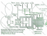
I was able to find a video showing how hydraulics are used to change propeller pitch. It seemed rather complex by itself, and it failed to mention how two hydraulic hoses are attached to a rotating shaft. How is this done and is it failure prone?
 
I was able to find a video showing how hydraulics are used to change propeller pitch. It seemed rather complex by itself, and it failed to mention how two hydraulic hoses are attached to a rotating shaft. How is this done and is it failure prone?
I think this video/model does a good job of showing how the mechanical engineering works.

However, it does not address how the hydraulic fluid is inserted into rotating shaft.
 
Last edited:
There is a babbitted sleeve that fits over the shaft with a groove for ahead and a groove for astern.
 

Attachments

  • Screenshot_20250521-192025.png
    Screenshot_20250521-192025.png
    879.1 KB · Views: 21
So a 40 year old ship which I could assume doesn't use the propellor 100% of the time anyway and might not go astern very often has the thrust lever either no changed or the pitch change mechanism breaks or gets stuck?

Does seem like a bit of risky manoeuvre that close to the bridge.
 
Controllable pitch is probably the most reliable method of reversing propulsion. Most big ships have to stop and start their engine in astern. Failures to start do happen.

Here is one that I can remember.

 
Most big ships have to stop and start their engine in astern.
Are they able to disengage the prop or do they have to start against the rotation of the prop?
I remember an old tugboat captain telling me about the brake that stopped engine and prop rotation before starting astern.
The rest of the story;
"The brake band touched the drum lightly and made an annoying noise. One day some idiot greased the brake to get rid of the noise. Unable to stop the rotation to go astern, they took out part of a wharf before they stopped drifting."
 
Cargo ships are almost exclusively slow speed diesel powered which use engines directly coupled to the propeller. There is no reduction gear. There is no clutch. There is no shaft brake. The engine uses high pressure air injected directly into the cylinders to stop and reverse rotation.

Engines with clutches and reduction gears have shaft brakes. Ships have a maneuvering speed range and a sea speed range. The engine doesn't need to be able to reverse the propeller at sea speed. Tugs, on the other hand, need to be able to reverse the propeller at all speeds hence the need for a shaft brake.

Interesting note, the propeller in astern only loads the engine at 50-67% of the ahead load at the same rpms. We recently ran into trouble with this because the engine manufacturer used a conventional propeller curve to emissions certify their engines and we can generate 100% load in all directions with our z-drives. This created stalling problems. Big trouble.

Steam turbine ships have an astern turbine. It's typically a 1 or 2 Curtis stage turbine that is capable of producing 50% of the power the 20+ mixture of stages (Curtis, Rateau, reaction) that make up the ahead turbine.
 
Last edited:
I was able to find a video showing how hydraulics are used to change propeller pitch. It seemed rather complex by itself, and it failed to mention how two hydraulic hoses are attached to a rotating shaft. How is this done and is it failure prone?
It's exactly the same thing as a Kaplan wheel in a hydro electric application, except that a Kaplan never needs to reverse, except maybe in a pumped storage application.
 
According to the always reliable Wikipedia the Cuauhtémoc is powered by a Cat D399, which is a 4-stroke engine. So it can only run in one direction, right?
 
4-strokes are are direct reversible as well. The engines I have worked with have forward and astern lobes on the cam. There is a ramp ground between the two. There is a pneumatic piston to push the cam axially into the forward or astern positions.

2-strokes typically shift only the injection pump timing for astern operation. Exhaust valve timing doesn't need to be optimized so it does not change from ahead. Modern 2-stroke engines are camless and may change the exhaust valve timing as well.

The D399 engine is a high speed engine and operates in the same manner as engines we are more familiar with. It's only special feature is that it is an indirect injection engines and gets terrible fuel economy as a result. The Cat 3500 series replaced the D398 and D399 engines.
 
Last edited:
4-strokes are are direct reversible as well. The engines I have worked with have forward and astern lobes on the cam. There is a ramp ground between the two. There is a pneumatic piston to push the cam into the forward or astern positions.
Cool, I didn't know that.
 
Interesting note, the propeller in astern only loads the engine at 50-67% of the ahead load at the same rpms. We recently ran into trouble with this because the engine manufacturer used a conventional propeller curve to emissions certify their engines and we can generate 100% load in all directions with our z-drives. This created stalling problems. Big trouble.
From what I have seen, propellor shape is optimized for ahead direction, and not astern, thus the difference in loading of engine based upon direction.

How is the Z-Drive overcoming propellor optimization for ahead vs astern loading of engine to evenly load engine in both directions? :unsure:

This image provides a hint.

1748018878258.png
 
Last edited:
It's only special feature is that it is an indirect injection engines and gets terrible fuel economy as a result. The Cat 3500 series replaced the D398 and D399 engines.
I'll attest to that. When I was with the micro grid, we replaced a pair of D398s with a 3516.
The saving in fuel was enough to make the payments on the 3516.
 
How is the Z-Drive overcoming propeller optimization for ahead vs astern loading of engine to evenly load engine in both directions?
The few z-drive applications that I have seen typically needed full thrust in any direction.
There are some exceptions to this, but motor loading is never a factor.
 
The few z-drive applications that I have seen typically needed full thrust in any direction.
There are some exceptions to this, but motor loading is never a factor.
Agree Z-Drives are Azimuth Drives and thrust is same no matter azimuth angle.

What I am waiting for is the TB.e Drive. 🥸
 

Part and Inventory Search

Sponsor