Navigation
Install the app
How to install the app on iOS
Follow along with the video below to see how to install our site as a web app on your home screen.
Note: This feature may not be available in some browsers.
More options
Style variation
-
Congratulations cowski on being selected by the Eng-Tips community for having the most helpful posts in the forums last week. Way to Go!
You are using an out of date browser. It may not display this or other websites correctly.
You should upgrade or use an alternative browser.
You should upgrade or use an alternative browser.
Maximum material condition on circular datum
- Thread starter E-N-E ENG
- Start date
B(MMB) is called datum feature shift and is NOT a bonus.
Only the circled M after Ø0.2 is called "bonus" (additional tolerance) and not the circled M after B (which again is datum feature shift)
Datum feature shift is offering additional datum feature mobility (giving back some datum feature mobility)
Do not add the datum feature shift to the "bonus" tolerance because that would be wrong (very wrong).....
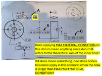
Technically the standard says preference is given to interpreting that as applying to the surface of the hole. That interpretation considers both the amount of material and any related tolerances of location or orientation.
In this case, since the Feature Control Frame references [ A | B ], then one needs to consider the orientation allowed on the datum feature [ B ] relative to [A]; however since that orientation allowance is 0 when B is at Maximum Material Condition (MMC), that related contribution is also 0.
The simulator for that datum feature is a perfectly oriented cylinder at diameter 10.0. As the hole loses material and gets larger the part is allowed to rattle around with whatever clearance it has if that will allow the related features to meet their position tolerance requirement.
An assumption that is made for CMMs is that an imaginary cylinder would expand in the hole to make enough contact enough to just barely lock into the hole and then the diameter of the cylinder would have the MMC diameter subtracted from it to give a diametral amount the part could rattle; however this is only guaranteed to work if the hole itself is of perfect form; it's a work-around for CMMs so the operators can make reports.
If the datum feature was referenced at Regardless of Material Boundary, then the axis would fix the part in position and prevent it from being moved to allow the related features to meet their position tolerance requirement.
- Thread starter
- #4
What if the datum B hole measures on the LMC side, dia. 10.6?
How does this affect the positional tolerance of dia. 0.2?
Let say the datum simulator is at exactly dia. 10.0, then does the positional tolerance would be off the axis of the dia. 10.0 or at the maximum allowable shift up to 0.6mm?
Thank you
How does this affect the positional tolerance of dia. 0.2?
Let say the datum simulator is at exactly dia. 10.0, then does the positional tolerance would be off the axis of the dia. 10.0 or at the maximum allowable shift up to 0.6mm?
Thank you
- Thread starter
- #5
What if the datum B hole measures on the LMC side, dia. 10.6?B(MMB) is called datum feature shift and is NOT a bonus.
Only the circled M after Ø0.2 is called "bonus" (additional tolerance) and not the circled M after B (which again is datum feature shift)
Datum feature shift is offering additional datum feature mobility (giving back some datum feature mobility)
Do not add the datum feature shift to the "bonus" tolerance because that would be wrong (very wrong).....
How does this affect the positional tolerance of dia. 0.2?
Let say the datum simulator is at exactly dia. 10.0, then does the positional tolerance would be off the axis of the dia. 10.0 or at the maximum allowable shift up to 0.6mm?
Thank you
The amount the datum feature can move rarely has a good calculation for the true-position shift. There are some cases that make it appear that way, but that is misleading.
At it's heart, true position is defined relative to the ideal datums; datum shift allows the part to move relative to the datum features, not to allow the holes to move relative to the true position of the holes. The true position of the holes remains fixed. The deviation from that true position is only due to the tolerance in the Feature Control Frame.
There is no sense in adding them and they do not affect each other.
- Thread starter
- #7
ok thanks. I will conclude that adding (M) on datum B does not change anything. B (M) = B.The amount the datum feature can move rarely has a good calculation for the true-position shift. There are some cases that make it appear that way, but that is misleading.
At it's heart, true position is defined relative to the ideal datums; datum shift allows the part to move relative to the datum features, not to allow the holes to move relative to the true position of the holes. The true position of the holes remains fixed. The deviation from that true position is only due to the tolerance in the Feature Control Frame.
There is no sense in adding them and they do not affect each other.
- Thread starter
- #9
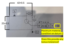
No.
First off because, in this case, C is a flat surface and has no size and has no maximum material condition.
Second because (M) indicates the datum feature can wander around it's own true position independently from the amount the feature which "bonus tolerance" applies to.
Which gets back to the first part - the flat surface, in this case, is not allowed to wander anywhere - it is to be placed in contact with a real or software generated mating planar surface.
- Thread starter
- #11
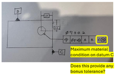
Assuming dimensions and tolerances are assigned but those should not affect anythingNo.
First off because, in this case, C is a flat surface and has no size and has no maximum material condition.
Second because (M) indicates the datum feature can wander around it's own true position independently from the amount the feature which "bonus tolerance" applies to.
Which gets back to the first part - the flat surface, in this case, is not allowed to wander anywhere - it is to be placed in contact with a real or software generated mating planar surface.

Correct?
Thank you
I'll be nitpicky -- that's not quite true. For a feature being toleranced with position at MMC (the four holes), that would be true. But a datum is always a theoretical plane, axis, point, or combo of those. With MMB, it just means that the theoretical axis is one that's derived from the feature as if it were at its MMB.Technically the standard says preference is given to interpreting that as applying to the surface of the hole. That interpretation considers both the amount of material and any related tolerances of location or orientation.
In your drawing, they won't affect anything because your datum is still just a plane taken from the right side of the part. If your datum feature were tagged with the span of 42 +/- 0.5 then the datum would be greatly affected: it would be a plane derived from the center of that span.Assuming dimensions and tolerances are assigned but those should not affect anything
Correct?
Thank you
This is a discussion about the modified datum feature reference not the datum itself. The datum feature simulator or true geometric counterpart has a fixes location which the SURFACE of the datum feature is not allowed to cross when (M) is used.
That's true for the boundary/simulator/counterpart; of course. But the initial question (highlighted in yellow in the first post) was whether the modifier affected DATUM B -- the "theoretical axis of the inner hole," to use the OP's phrasing. Thus, it's probably best to answer the question based on the same terminology and thinking that the OP was using.
Since one cannot apply any modification to a datum, and it is applied to a datum feature reference in the Feature Control Frame, the best interpretation is about the datum feature and the surface of the datum feature and not the theoretical center of the datum that is derived from it. Don't support the inexact interpretation of the OP.
Similar threads
- Replies
- 6
- Views
- 3K
- Replies
- 8
- Views
- 13K
- Locked
- Question
- Replies
- 17
- Views
- 3K
- Locked
- Question
- Replies
- 18
- Views
- 2K
- Question
- Replies
- 25
- Views
- 25K


