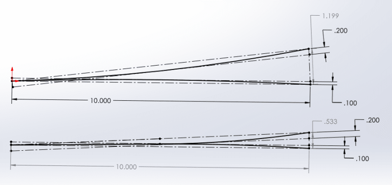
I have to restrict/clarify my previous comment in which I confirmed that the sum of flatness tolerances is a reasonable way to evaluate the maximum gap, and say that it is true when the two faces are the main interface between the parts, meaning it is where the greatest mounting forces act and it is what orients the parts relative to each other. Speaking in dimensioning and tolerancing terms, it is when these surfaces are most likely to be selected as the primary datum feature for geometric tolerances on each respective part, constraining 2 rotational degrees of freedom, and have a flatness tolerance controlling their form. This is what I think the most relevant case for the OP's question is, so my answer is intact. But if from some reason the flatness tolerances are applied to surfaces that do not mate as the primary interface and there is more prominent constraint in the assembly - it is a different story and the gap might increase by the effect of the orientation errors between these faces and the primary mating faces. But that would be a rare and questionable application of flatness tolerances to begin with.
As for the rocking issue that was brought up by chez311 - usually, primary interface surfaces are clamped together by fasteners located more or less symmetrically to the center of the contact area. In such case, the mechanics of the process should balance the surfaces to the condition of minimum separation, and I believe the sum of the flatness errors is a good estimate for the said minimum separation gap. On a small part, even a single fastener designed to act at the center of the contact areas should do. This should make the effect of rocking on the functional assembly insignificant. I think rocking is more a free-state inspection issue for which there are the known ASME Y14 supported solutions such as the "single solution", "candidate datum set", etc.
Speaking of free-state, there is also the rigidity issue brought up in the last post here. Inspecting the parts for flatness in the free state and deriving from that the maximum gap expected, is actually the stringent (worst case) evaluation, when considering the expected effect of flexibility of the parts and the actual clamping forces at functional assembly. The actual gap can only become smaller than what the sum of flatness tolerances gives.

