Continue to Site

Eng-Tips is the largest engineering community on the Internet

Intelligent Work Forums for Engineering Professionals

  • Congratulations 3DDave on being selected by the Eng-Tips community for having the most helpful posts in the forums last week. Way to Go!

Masonry basement - horizontal concrete tie/beam 1

Status
Not open for further replies.

n3jc

Civil/Environmental
Nov 7, 2016
189
I think this is a question for engineers from EU.
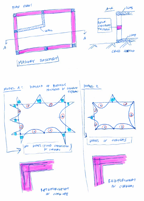
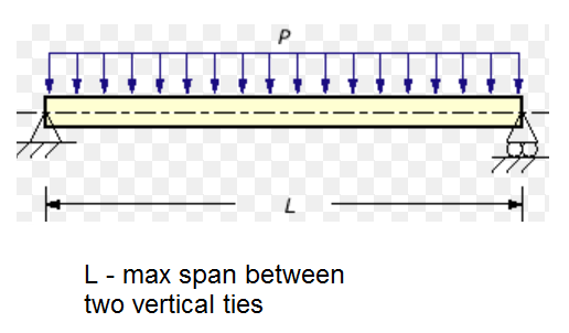
We have masonry basement, so we need to make horizontal concrete tie/beam at 1/3 height of the masonry basement wall. This concrete tie is needed because of horizontal forces (soil pressures).

Im wondering which model is correct?
1.) there is no node in corners - fixed connection between ties/beams from differen directions
2.) there is a node

Its imporatant because the diagram of bending moments is very different in both casses.
What do you suggest?

basement_masonry_oqgeow.png
 
Replies continue below

Recommended for you

Why can't the masonry be made to span slab to slab instead of using a tie-beam?
 
In both cases i'll consider corners as nodes. Beams reaching a node can be fixed or pinned.

I think both models a almost OK based on the steel reinforcement. But considering that the force is "closing" the corner both of your steel bar details will behave as a continuos beam between members at corners, especially the left detail. The right one probably won't develop full rotation restrain.

Consider a proper stirrup detail at corners in order to maintain node integrity and also place some shear transfer between masonry and tie beam.
Masonry will bend too when subjected to the triangular soil pressure and if there is underground water you will have to consider a larger pressure.

Why do you have a pinned node at midspan in bottom beam?

A better model is to consider that corner is continuos, not fixed or pinned. The beams that deflect outward (respect the basement) will push against the soil and will have a higher K coefficient for horizontal loads. But before to take this into account i will check the load and resistance of the members without that outward effect and then evaluate if necessary with respect to the margin of over resistance and loads level.

Try to get this file through google.
Guidelines and Rules for Detailing of Reinforcement in Concrete Structures -ANNELI DAHLGREN
LOUISE SVENSSON.
This will give you some guide about reinforcement detail.
ACI 318 will show you how to detail stirrup.
 
I would consider ties as pinned in the corners. Also vertical ties as pinned top and bottom (slab-tie connection).
 
Ytyus tnx for your long elaboration. I appreciate it.
"Why do you have a pinned node at midspan in bottom beam?" Well the vertical tie is not supported by a wall so its not rigid, its flexible.. there is a negative bending moment there but it so small i wasnt drawing it...i made a model in tower 6 program.

molibden - why would you consider vertical ties as pinned at the bottom? I think fixed is more accurate?

Also - the only vertical ties for which i have to calculate sufficient reinforcement are the ones who are not supported by a wall, right?
For all vertical ties that are in corners or at crossings of the walls dont need that?
 
Pinned so you get more reinforcement on the inside of the tie. In my opinion it's safer.
Also if you design a rigid connection with the slab, then you have to provide additional reinforcement in the slab to fully transfer moment from tie to slab.
 
If masonry walls loads produce unequal reactions the corner will twist. At least consider torsion i.e. closed stirrups.
Also masonry and concrete column will need a shear bond. And probably masonry will need at least longitudinal rebar for out of plane bending, considering that masonry weight is not brutally high the only vertical component that is stabilizing the out of plane loads will be the upper slab reaction on walls, If the vertical reaction is small compared to the horizontal pressure the final reaction will act outside the middle third of the bottom wall width and you'll need a wider wall. And on another perspective,if the vertical load doesn't eliminate tension (-P/A+My/I>0)it will need vertical reinforcement into masonry.

Closed stirrups at cornes probably will also be enough for shear and twist, i'll check this depending on the basement height.

the crossing walls will be in-plane pushed and subjected to shear, and the columns must consider that in design. This displacement will also introduce bending at columns. Taking into account that upper and bottom slabs are restrained to horizontal displacement (if upper is at ground level) the vertical ties (columns) can be considered as pinned at both ends.

Pinned or fixed bottom depends on the foundation scheme. The upper end can be considered as pinned because it is difficult to achieve a true rotational restraint between slabs and column, I'll only take continuous approach if there are beams under the slab at the top of the column with proper orientation.


Great posts! tnx for help.

As Ytyus said - Masonry will bend too when subjected to the triangular soil pressure so there is a need for a shear transfer between masonry and tie beam. How do they do that? Any detail? Do they connect vertical reinforcement from the masonry wall to the reinforcement of the horizontal tie or something? I have never seen this in real life.

About calculating reinforcement of horizontal tie - I have seen some calculation from other engineers and most of them use a model like this:
they took the longest span between 2 vertical ties (it doesnt matter if vertical tie is in the corner/in the middle of the wall or supported by a crossing wall) and then calculate it as a beam:

1tie_k2qnnz.png


Then they calculate sufficient reinforcement based on that model and thats it for an entire horizontal tie...
they do not model it as continues beam which kinda bothers me...

what is your opinions on that model? Too simplistic?
 
n3jc said:
Masonry will bend too when subjected to the triangular soil pressure so there is a need for a shear transfer between masonry and tie beam
What is the height of the masonry? Most basements (in the states anyhow), would use reinforced masonry to span slab to slab unless it was simply not practical.
 
I agree w/ XR250, the cmu will span in the shorter direction whether you design it that way or not. Force follows stiffness. If you want the wall to span horizontally, design it to span between vertical piers in the masonry. The vertical piers are designed as "beams" within the thickness of the wall. If you are designing the cmu to span horizontally, adding a horizontal beam at 1/3 of the wall height will not do anything for you.
 
Well im open for new ideas... but why is it that this is a standard practice in EU for masonry basements?
BTW basement walls are cca 3 m heigh (300 cm).
 
n3jc said:
Well im open for new ideas... but why is it that this is a standard practice in EU for masonry basements?
I don't know. I don't know why you some of you guys drive on the wrong side of the road either [bigsmile]
3 m. should not be a problem for reinforced masonry unless the lateral pressures are really high from hydrostatic, surcharges or being buried deeper than 3m.
 
Not everywhere know what reinforced masonry is.

n3jc do it like you planned. Masonry wall will span between slab and horizontal tie with no problem. I would even position hor. tie more towards mid-height. Vertical tie will be the critical one as it's shorter (stiffer).

If you have hydrostatic load then this is a no-go and build a RC wall.
 
Google this file for guide, think will clarify you some details.
21359-fir-cantilever-masonry-retaining-wall-brochure_2014

Cantilevered or simply supported wall has higher pressures at lower side, I think a short 1 meter depth wall under the tie beam may be influenced mainly by shear instead of bending. I have read some code time ago that stated that bond between rebar and mortar inside masonry isn't really provided so i'll better rest on shear action (just an idea). Any way this bond will improve if you add some gravel sized enough to fit into reinforced masonry holes.

How do you check out of plane bending if there is partially composite action?

 
Status
Not open for further replies.

Part and Inventory Search

Sponsor