Continue to Site

Eng-Tips is the largest engineering community on the Internet

Intelligent Work Forums for Engineering Professionals

  • Congratulations waross on being selected by the Eng-Tips community for having the most helpful posts in the forums last week. Way to Go!

Looking for provisions for loaded concrete edges

Status
Not open for further replies.

H.Stone

Civil/Environmental
Feb 13, 2020
2
Hello - I’m wondering if anybody knows about any provisions from AASHTO, ACI, or others for dealing with edge loading of concrete? Looking at AASHTO, all I find regarding bearing is in AASHTO 5.7.5 which seems of which seems insufficient for my situation as described below.

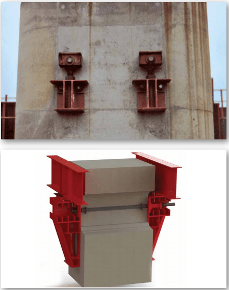
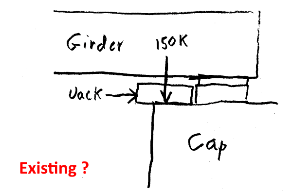
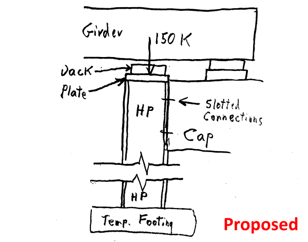
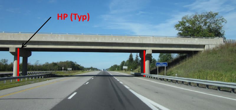
The project I'm looking at involves jacking highway bridge girders so their bearing pads can be replaced. Unfortunately, there is only a flat surface of 4” of concrete behind the grider shoes to place the jacks; this is too little as the 100-ton jacks are 6” in diameter. The current idea is to temporarily anchor an HP-section to the side of the pier and weld a PL 2”x16”x16” bearing plate to top. The plate would be positioned so it laps over the 4” of concrete. The jack would then be positioned so it sits over the 4” of concrete and 2” sitting over the HP-section; in the end the center-of-load will be sitting 1” from the bent edge.

I’m concerned about loading such a small area of concrete so close to the edge. The load will be ~150-kips once factored. The HP-section anchorage cannot support much load as the connection is sensitive to concrete breakout, so maximizing the bearing on the concrete is required. Per AASHTO 5.7.5 for bearing, a 4”x16” area of concrete should support ~220-kips minimum, but given how the load is positioned it doesn't feel right taking that as the final answer (the risk of spalling or break-away comes to mind). I appreciate any leads or ideas anyone might have. Thank you.
 
Replies continue below

Recommended for you

H.Stone - This sketch is my interpretation of exiting conditions with jack location included:

Jacking_Plan-1-600_h39umw.png


Frankly, I would not use a bracket/plate/cap support for two reasons, even if in the unlikely event there is an obscure specification provision that says this is acceptable:

1) If the bracket "slips", all load is on the 4" lip of the cap.

2) A good portion of the cap's lip, including the centroid for application of the jack's load, is on what I consider unreinforced concrete rebar cover. Whether required or not, I have always applied loads to concrete within limits of the rebar cage.

If practical, I would extend the proposed HP to ground, on a suitable temporary footing, with slotted connections to the cap. Therefore any settlement of the jack/HP/temporary footing under load is not an issue:

Jacking_Plan-2-600_lsx7lx.png


[idea]
 
If this is the Pier Cap, can you through bolt and place stiffened large angle sections either side? This way you can place your jack completely on the angle.

You won't have to worry about concrete breakout. But drilling/coring through the cap might be the most difficult part.

At the abutment, it will be slightly trickier. Post down to the footing like SlideRuleEra suggested?

Are these steel or concrete girders?

If steel, just watch the change in bearing location relative to the bearing stiffeners.

AASHTO 2017 5.6.5 is always what I use, but I take that with a huge grain of salt as I am never too confident with those equations involving large concentrated forces near to the edge of concrete. I trust them much more if I know the load will be concentrated at least inside the clear cover concrete.
 
Regarding to your question on ACI provisions on concentrate load bears on edges, you can find the answer from ACI318 CH.11 - Design of Corbels (under provision for shear friction). Once worked out required bearing area, I usually assume a critical shear plane that lies approximately 20° from the wall face, then check whether the reinforcement within the plane has adequate strength to prevent the concrete breakout. Don't ask me for reference of the failure plane, it was a study published long time ago, and I have used it many times.
 
SlideRuleEra - That's a very accurate sketch of my situation, and a very simple way to solve the problem.

STrctPono - Only need worry about steel girders at the bents this time. I like the idea of sandwiching the pier-cap and keeping everything up-top.

Both solutions are good ideas and I like their respective advantages. I'll investigate both and see which is most feasible. Thank you both for your help and insights. Keeping bearing loads within the reinforced section makes good sense the more I think about it.

retired13 - Thanks for pointing me to that ACI section and advice. I'll look into it too.
 
H.Stone said:
I'll investigate both and see which is most feasible.

Your question has "ring" of being part of a Contractor's "Means & Methods".

If you are a Bridge Engineer, strongly suggest that you allow a Contractor the option of submitting their own proposal for your unbiased evaluation and approval, no matter which plan you come up with.

If you are, or represent a Contractor... forget I made this comment [noevil].

[idea]
 
Think how shoring companies like EFCO and Dayton Superior do it when they are pouring pier/bent caps. It doesn't have to be such an elaborate structural section like these but the concept is the same.

Untitled_ck4cyb.png
 
@H.Stone,SRE’s scheme is what I commonly see and do. Another thought, can you jack against the end diaphragms from the bridge seat? Sometimes it’s doable. In some cases you need to add stiffeners and reinforce the connection.

Not too long ago, I had a project where two rockers had to be replaced on a 5’ square column. The loads were ~300 k each. The column was in between two railroad tracks. Since we couldn’t use shoring we enlarged the top of the column; drilled through the column to install 15 tie rods. It worked but drilling was a ¥!+€#. We have another project on the same line where we’re doing It again.
 
I guess the big question then is what is your access like?

If it's over water or has really tall piers... posting down won't work.

If it's a typical grade separation bridge, then posting down probably wins out in cost.
 
Another thought, can you jack against the end diaphragms from the bridge seat?

We have gone as far as letting the contractor drill extra holes in the connection plates to mount a temporary diaphragm for lifting (a pair of channels bolted back to back on either side of the connection plate). We included some 'leading' notes to hint at the option in our plans.

Rod Smith, P.E., The artist formerly known as HotRod10
 
Status
Not open for further replies.

Part and Inventory Search

Sponsor