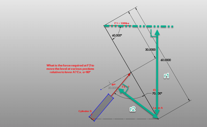
Both of these forces have two components projected onto the lever arm coordinate system. One of the components is parallel with the lever, the other component is perpendicular to the lever. Only the perpendicular forces need to be included when summing the moments about the hinge (the other components are inline with the lever and cause no moment).
If you write you the perpendicular components of force in terms of the respective angles, you can setup a system of equations and solve.
For example,the perp. component of F2... F2perp = F2 cos (alpha). F1perp = F1 sin (60).
Not clear if the angle for F1 stays constant or if the force is supposed to stay horizontal. Lets just call the 60 deg, beta. Then F1perp = F1 sin (beta).
If you do it this way then r1 and r2 become constant.
Some geometry is needed to solve the angles in terms of each other. In fact I think you would need to have the offset of the hinge at the base of cylinder B to properly express this. If the angles arent changing it become easier.
You can simply sum the moment about the hinge and only include the perp. components. 0 = F2perp*30 - F1 perp*60 ....> F2perp = F1 perp*60/30 ...> F2 = F1 perp*2/cos(alpha) ...? F2 = 2*(F1 sin(60))/cos(20) = 184.3 #.
If you can solve the relationship between alpha and beta, then you can write them up as an equation and solve the same equilibrium equations parametrically and prepare a graph of F2 vs alpha.

