zsa,
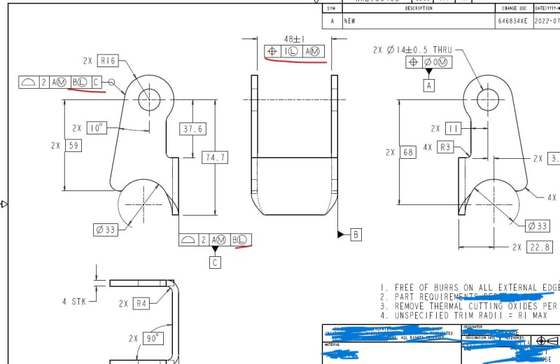
As others indicated, perpendicularity should have been used instead of position to control the 48+/-1 width with ref. to datum feature A.
It is applied at LMC and there are actually two possible methods to verify conformance to this control.
One is called the surface method, and it requires that the feature doesn't invade a boundary inside the material, of a width that equals to 49(the LMC size)+1(the perp. tolerance at LMC) = 50 mm, which is perfectly perpendicular to the datum axis derived from datum feature A. This method is the one that represents the design intent of such specification better. Perpendicularity at LMC is used when there is a need both to orient a feature of size relative to a datum, and maintain some limit beyond which material should not be removed or absent.
The other supported interpretation is related to controlling the center plane for fitting between two parallel planes tolerance zone oriented perpendicular to the datum. It's a bit problematic because there is a slight difference between related ASME standards with regard to how to obtain that center plane, but considering the design intent I described above (ensuring enough material at the sides of the slot) and what now clearly specified in the new standard on measurement data reporting (ASME Y14.45) the controlled center plane for an internal width (slot) is the center of two parallel planes of the minimum separation, that will contact the lowest points on the two actual surfaces (this means the planes for the center plane derivation are inside the material). In the Y14.5 language, it is called the "unrelated actual minimum material envelope". See an illustration in this
link. The size of the tolerance zone is dependent on the size of the actual slot, but more precisely, it is dependent on that same "unrelated actual minimum material envelope" as described above. So, when this envelope's width is equal 49 the tolerance is 1 mm as specified in the feature control frame. You get more tolerance ("bonus") as the envelope becomes smaller, and that means 2 mm of perpendicularity tolerance for 48 mm size, and 3 mm tolerance for 47 mm size (the specified 1 mm plus the amount the feature's envelope is smaller than the LMC limit).