Continue to Site

Eng-Tips is the largest engineering community on the Internet

Intelligent Work Forums for Engineering Professionals

  • Congratulations KootK on being selected by the Eng-Tips community for having the most helpful posts in the forums last week. Way to Go!

Lateral Pressure of Flowable Fill concrete against a basement wall

Ron247

Structural
Jan 18, 2019
1,196
I have a situation where a house transitions from a crawl space to a basement. The crawl space area immediately adjacent to the basement wall was not backfilled and the first row of interior piers for the crawl space are very close to the 8'+ drop-off. There has been soil sloughing off over time near the piers.

I told the Owner of the possible remedies, and they decided they want to fill the area with flowable fill. I have suggested doing it in 3-4 lifts and letting each lift set up before installing the next lift.

I have questions:
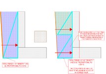
  1. Am I correct that once the concrete cures, the lateral form pressure from that pour is no longer present against the concrete basement wall other than any lateral soil pressure from the embankment that may have "shifted" during the pour?
  2. I recommended placing plastic across the bottom and up each side at least equal to the total pour height to help prevent liquid/flowable fill from seeping into the finished basement area due to the pressure. Is that reasonable to expect? It looks like the concrete wall sets on stone, not a concrete foundation.
  3. I did not design the concrete wall but it was a manufactured product that was installed by the supplier. I am having owner's get confirmation from supplier it is designed for lateral soil loads of the expected height. Is there more I should have them confirm?
  4. The finished floor above is wood. I have recommended well ventilating the crawl space during curing to minimize effects from the heat and moisture from the drying process of the flowable fill. Is that a reasonable expectation.
  5. Anyone ever do this before, and if so, what problems did you encounter?
Any advice is greatly appreciated.


1747065937568.png
 
Replies continue below

Recommended for you

Here's my logic, and I'm totally happy to be corrected by someone smarter than me....

When the grout is poured in it has effectively zero stiffness so all resistance is provided by the wall which causes it to bow out under the pressure
This shape is maintained as the grout slowly cures
Once cured, the grout is very strong and will stand together in its own shape without needing to push on the wall
The wall therefore tries to relax back to its original (vertical) shape - however, the grout now restrains it
The grout therefore ends up in compression resisting the load from the wall trying to undo its deformation
Presumably the compression profile looks very similar to the original fluid pressure profile, but it has flipped from grout pushing the wall to wall pushing the grout

Yep, until something moves an infinitesimal amount, at which point the load vanishes, so it's effectively irrelevant once the concrete is set. I.e. you needn't design for it which is what OP seems to be enquiring about. We seem to agree on that.

I typically specify these repairs in ~600mm lifts, which most contractors seem happy with. Sometimes prop too. It depends. It depends on the mix too. If they can use a stiffer concrete it's not as critical as a highly fluid self levelling mix.
It's not irrelevant and you do need to design for it as there is an intermediary case of the wet grout against the wall
This will apply load to the existing structure and will cause it to deflect - you need to be sure that this works
 
I'm not totally convinced either way on this, but still struggling to see how the pressure is somehow relieved after curing.
Because the wall can't move without the pressure vanishing. For a load to matter it has to keep applying load. It has to be capable of doing work.
 
You design for the wet grout. But the pressure from the cured grout and the subsequent wet grout isn't additive.
I half agree
The deformed shape from the first pour will still be present as the wall cannot relax back to its unloaded state due to the solid grout preventing it
The load from the 2nd lift will add to this deformed profile - it would be weird to model
However, as your 2nd lift is (say) half the height, the load will be significantly reduced (50%) compared to doing it as 1 lift

My attempt at a scientific sketch below
1747101452927.png
 

Attachments

  • 1747101391237.png
    1747101391237.png
    361.2 KB · Views: 0
  • 1747101435448.png
    1747101435448.png
    351.9 KB · Views: 0
Yeah, I disagree, you don't get the saw tooth thing develop. You can't "add" to the deformation from the first lift, because as soon as any additional deformation occurs, the bottom tooth vanishes. It doesn't keep pushing.
 
From 3 years ago, I outlined the only things I could think of as reinforcement/repair methodology. These were what I came up with at that time.
  1. Install a backup support system in case of failure of the embankment. It would be the 2 rows of beams, 1 set of tall piers near the embankment and 1 set of piers setback enough to accommodate the difference in height. I did a preliminary design for budget purposes.
  2. Fill the area with some material. Stone, soil, flowable fill etc. Basically, what we are discussing now.
  3. Build a reinforced block retaining wall near the embankment that had the top of the new wall secured laterally to either the floor above or strutted over to the original basement wall. It would have a narrow strip footing and not be a cantilevered retaining wall. Then the void between the new wall and the soil would be grouted in 2 or 3 lifts. For this option, the existing uneven soil in the missing backfill area would get distributed/evened out. Right now the elevation changes about 12" to 18" in some areas. I would form up the footing on top of the soil and dress it up for sliding later before pouring the void. Dressing it up would require pouring a housekeeping slab between the new wall and existing concrete wall.
Are there any other reasonable options that anyone can think of?
 
Yeah, I disagree, you don't get the saw tooth thing develop. You can't "add" to the deformation from the first lift, because as soon as any additional deformation occurs, the bottom tooth vanishes. It doesn't keep pushing.
Yep I get you. It's a headache to think about and I'm not 100% sure that there isn't some additive nature of it....
As that gap opens up though new grout will fall into it...does that affect any of the loading??
 
From 3 years ago, I outlined the only things I could think of as reinforcement/repair methodology. These were what I came up with at that time.
  1. Install a backup support system in case of failure of the embankment. It would be the 2 rows of beams, 1 set of tall piers near the embankment and 1 set of piers setback enough to accommodate the difference in height. I did a preliminary design for budget purposes.
  2. Fill the area with some material. Stone, soil, flowable fill etc. Basically, what we are discussing now.
  3. Build a reinforced block retaining wall near the embankment that had the top of the new wall secured laterally to either the floor above or strutted over to the original basement wall. It would have a narrow strip footing and not be a cantilevered retaining wall. Then the void between the new wall and the soil would be grouted in 2 or 3 lifts. For this option, the existing uneven soil in the missing backfill area would get distributed/evened out. Right now the elevation changes about 12" to 18" in some areas. I would form up the footing on top of the soil and dress it up for sliding later before pouring the void. Dressing it up would require pouring a housekeeping slab between the new wall and existing concrete wall.
Are there any other reasonable options that anyone can think of?
Genuinely I don't understand why you don't just do a timber pole wall and fill the void with drainage chip behind it
It looks like you have a heap of working space and it doesn't look like a very long wall - you could get an auger in there and get the job done pretty easily
 
The absence or presence of the wall pressure is my main concern. Adding full pressure of this magnitude to a relatively new existing structure bothers me. Due to construction errors I have seen in this residence other than the ones we are discussing, I have problems "relying" on all the things I cannot see being up to par.

If I believe that full pressure would exist, I would scrap this option. I have read articles before that say it gets reduced with time and have even seen graph somewhere of pressure versus time. The time scale was in hours like 100 or so. But, like everything these days, I also find information that it is not that way.
 
Genuinely I don't understand why you don't just do a timber pole wall and fill the void with drainage chip behind it
Could you better explain the timber pole wall. I am not able to visualize the concept.
 
I'm not 100% sure that there isn't some additive nature of it....
You can design it the saw tooth way if you prefer. There's nothing wrong with that. It's conservative. But not theoretically necessary.

Typically when doing these I tie the new concrete to the old wall, so the cured concrete and the old wall is one mass as far as overturning and soil pressure is concerned. The only thing that's going to fall over is the combined grout/wall structure. With each lift, the whole thing is stronger.
 
Could you better explain the timber pole wall. I am not able to visualize the concept.
Here's my scientific sketch
Your contractor will bitch and moan, as they like to do, but it looks realistic from the photo?
Depends if there is enough room to get a 2-2.5m high pole in there
Otherwise, I think this looks a lot easier than the wall my Dad and I just built at home so I back any decent contractor to get it done

1747103878307.png
 
As usual, everything below is per AI, so consider the source and the fact AI can gather the incorrect information more efficiently and better organized than humans. Where it gets this chart from I do not know, but it looks very similar to the one I saw years ago.


No, once concrete hardens (cures), it no longer exerts lateral pressure on the formwork in the way it does while it is fresh (plastic).
Here's why:
  • Plastic concrete (i.e., freshly poured) behaves like a fluid and exerts hydrostatic pressure laterally on formwork. This pressure is highest at the bottom of the form and increases with the depth of the pour.
  • After it sets and hardens, concrete becomes a solid material and no longer acts like a fluid. The lateral pressure drops to zero, provided there are no external forces or shrinkage stresses acting on it.

However:​

  • If the forms are removed too early, the concrete might not have gained enough strength to support itself, especially in vertical or cantilevered elements.
  • Residual form pressure can exist briefly due to expansion, temperature changes, or chemical reactions (like delayed ettringite formation), but it's not the same as the hydrostatic pressure from fresh concrete.

In standard practice, once concrete has fully set, lateral pressure on forms is negligible or zero, and forms can be safely removed per curing guidelines.


Would you like a chart of lateral pressure over time after pouring?

Here's a chart showing how the lateral pressure of concrete on formwork decreases over time after pouring. As the concrete sets and hardens, the pressure rapidly drops—typically becoming negligible within the first 24 to 48 hours, depending on the mix and conditions.


1747104110750.png
 
Here's my scientific sketch
I see the concept and will pose it to them as a good alternative. Thanks. I assume you concrete the poles into the ground.

Have you ever strutted the top back to the floor system or adjacent wall as an alternative to completely relying on the cantilever? I would think after you put your drainage chip in place, any strut you add at that point would only strut load if the embankment actually failed.
Yes you concrete them in, it's just a standard cantilever timber retaining wall but it's a solution I've seen a few times in similar subfloors here
I've never strutted it but it could be a good option if there's enough capacity in the existing structure - you could reduce your embedment and provide the failure safety mechanism using the house
 
It just dawned on me, of the few times I have seen tall forms removed, I have never seen a whaler or brace take off like it was shot out of a cannon or spring-loaded. I think I will pay more attention in the future and ask those guys what they have encountered.

Thanks to everyone for the help.
 

Part and Inventory Search

Sponsor