Continue to Site

Eng-Tips is the largest engineering community on the Internet

Intelligent Work Forums for Engineering Professionals

  • Congratulations IRstuff on being selected by the Eng-Tips community for having the most helpful posts in the forums last week. Way to Go!

Large live load on floor that's supported on a perimeter socle beam

Status
Not open for further replies.

nivoo_boss

Structural
Jul 15, 2021
137
Hello everyone!

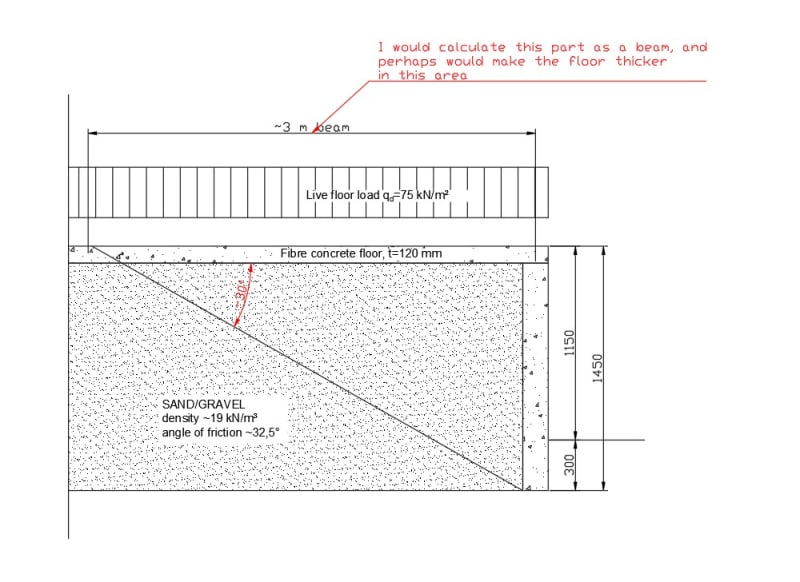
Perhaps you can give some advice. So I have this storage building with very large live floor load (design load is 75 kN/m²) and the floor is about 1,15 m higher than the outside of the building. The socle is made of insulated RC sandwich panels. Because of the height difference, the horizontal pressure to the socle from this live load is massive, roughly half of the vertical value when considering it as at-rest pressure and about 30% when considering it as active pressure (which is still a lot).

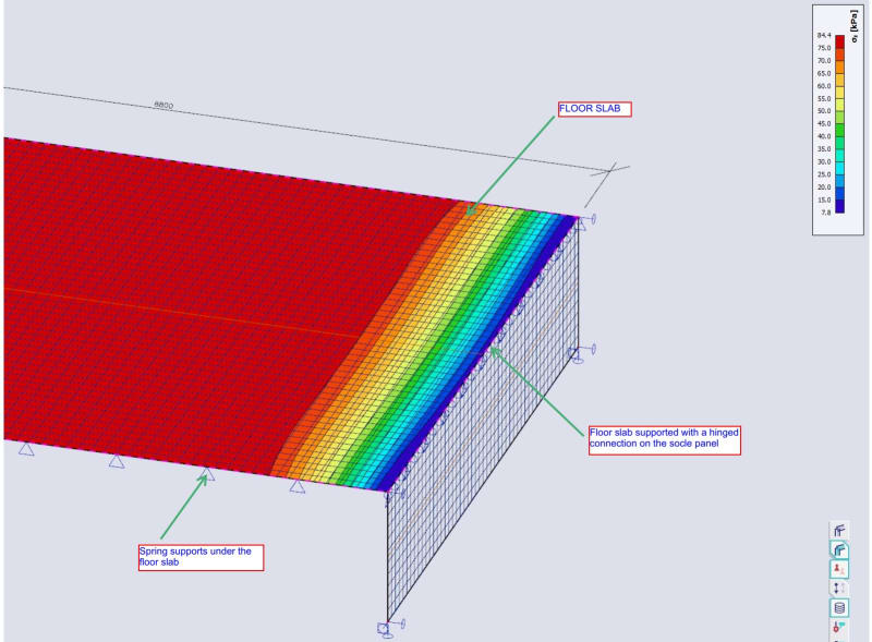
I can design the socle sandwich panels as ribbed plates to take this massive load but then the columns that are connected to the socle take these huge reactions of this beam and it makes the columns and pad foundations absurd (think a moment of around 350 kNm and horizontal load of ~350 kN to a pad foundation). So the idea is to support the floor plate with the socle beam so it would take some of the vertical live load from the floor. And finally to my main question - from how large area should I take this vertical load and apply it to the socle beam vertically? Below is a sketch of the situation. There is a floor joint at a distance of about 8,8 m from the socle. I'm thinking that considering this 8,8 m as a span for a floor slab is a bit too much.
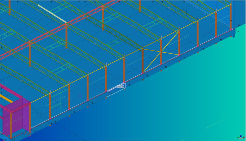
socle_k7ahfc.jpg
 
Replies continue below

Recommended for you

Can you remove the EPS and replace the top say 1.5m of sand/gravel with concrete. Then the load goes straight down and the perimeter is not required to retain this massive surcharge.
 
That would be insane :) The client would probably find a new designer. It would take a huge amount of concrete. The perimeter is around 120 m long.
 
120mm suspended slab vs 75kPa load isn't promising for any significant span.

A few ideas to consider:

Use the slab.to tie the top of the wall back. Depends on whether you can rely on friction between the active wedge and that joint.

Piers under the slab 1-2m behind the wall. Slab spans from wall to piers. Thicken slab as needed.

As above but strip footing 2-3m behind wall.

Add footing to base of wall (L wall).


I would design the perimeter as retaining wall with continuous footing..

If you post the structural plan you may get better responds ..
 
I'll add screenshot from the model. So the blue ones are the panels between the orange columns.

screenshot1_gumilc.jpg


I've had the retaining wall idea myself for some time, the client doesn't like it though. It would take some to lay/cast as opposed to the prefab panels.
 
"I've had the retaining wall idea myself for some time, the client doesn't like it though."

The only options I see to solve your issue are:
a) Add a footing (of sufficient size to resist bending and shear, to resist overturning, and to deflect minimally) to the wall, and (probably) make it thicker: if your drawing is to scale, that wall seems to be <=200mm thick, which seems to be on the low-end for strength and deflection.

b) Add diagonal (45 degree) supporting permanent "shoring" beams to the wall, with sufficiently tight spacing, and anchor them into a thin bottom slab that connects to the wall. This will make your wall much stiffer (from cantilever to a simply-supported beam, essentially), and require a smaller footing than a cantilevering wall.

You should also model the slab appropriately, using e.g., winkler springs. It will not be very stiff (in fact, with that thickness, it will deflect and thus bend a lot from any load that has even the slightest non-uniformity (i.e., a realistic load); at first glance I doubt that 120mm concrete with only fiber reinforcement will do the trick.

Finally, I advise you to be confident in your abilities and calculations. The client may "not like it", but unless you can use calculations and sound engineering judgement to propose a solution, it will not satisfy strength and serviceability requirements and as a consequence you may - in a worst-case scenario - be liable for damages or be harassed by the client in some other way during and after construction.

Your client cannot achieve the impossible by asking a competitors for the impossible or by simply saying "I do not like it". Politely communicating this to the client can be a challenge, but it must nevertheless be done in some situations.

PS. This project seems to involve an industrial building, and therefore ought to have project managers who know something about construction or engineering in general, which in turn means that the client should be able to listen to sound reasoning.
 
75 kPa is the design load, characteristic is 50 kPa. It comes from storage of doors that are stacked on each other and also from some really heavy machinery.
 
"You should also model the slab appropriately, using e.g., winkler springs. It will not be very stiff (in fact, with that thickness, it will deflect and thus bend a lot from any load that has even the slightest non-uniformity (i.e., a realistic load); at first glance I doubt that 120mm concrete with only fiber reinforcement will do the trick."

You mean that the floor will deflect near the sandwich-panel thus still compressing the subsoil and creating lateral pressure?

But what about this as in the picture below? I would design the ~3 m area as a beam that's on one end supported by the socle and on the other by the soil - length is derived from the angle of friction of the subsoil which is around 30°. But the "beam" should be extremely stiff or it can't have any soil beneath it or it will deflect and still apply pressure to the socle.

socle2_isiqnm.jpg
 
"You mean that the floor will deflect near the sandwich-panel thus still compressing the subsoil and creating lateral pressure?"
I mean that the floor will deflect everywhere; more at any intersections to columns, walls or concentrated loads, and less elsewhere. A thin (and thus not stiff) slab loaded by heavy machinery and stacked heavy items will behave like a "beam floating on water", at least approximately.

"I would design the ~3 m area as a beam that's on one end supported by the socle and on the other by the soil - length is derived from the angle of friction of the subsoil which is around 30°."
The slab will experience heavy machinery and stacked doors not only next to the wall, but also elsewhere, so that is not a complete solution to the slab design.

Furthermore, that distance is not related to the boundary conditions of the beam. There is only a pinned end at the wall (it will takes some moment if you add some rebar from the floor slab into the wall panel), and a discrete series of springs (representing the lateral stiffness of the soil) supporting the floor slab.

"But the "beam" should be extremely stiff or it can't have any soil beneath it or it will deflect and still apply pressure to the socle."
The pressure on the socle comes primarily from the soil, not from the floor slab; this was my impression, since you have not mentioned any significant vehicle or machinery loads located in the immediate vicinity of the walls. The only load transferred to the wall from the floor slab is a small vertical reaction directly above the wall, and a horizontal (lateral) shear force that highly depends on how much the floor slab is allowed to move horizontally.

PS. If you have any heavy machinery in the building, it will create point loads and/or line loads, which will cause the floor slab to generate large deflections, bending moments and shear forces in the vicinity of the point load. Assigning only a uniform pressure loading on the floor slab is not realistic.

 
"I mean that the floor will deflect everywhere; more at any intersections to columns, walls or concentrated loads, and less elsewhere. A thin (and thus not stiff) slab loaded by heavy machinery and stacked heavy items will behave like a "beam floating on water", at least approximately."

I'm not designing the overall floor, it's done by a floor designer. Should I doubt in her/his abilities?

"Furthermore, that distance is not related to the boundary conditions of the beam. There is only a pinned end at the wall (it will takes some moment if you add some rebar from the floor slab into the wall panel), and a discrete series of springs (representing the lateral stiffness of the soil) supporting the floor slab."

What if there is basically an empty space under the slab in that 3 m span, without the springs/soil, I mean? Shouldn't it then act as a beam?

"The only load transferred to the wall from the floor slab is a small vertical reaction directly above the wall, and a horizontal (lateral) shear force that highly depends on how much the floor slab is allowed to move horizontally."

I did a small model of the situation. I added a floor slab 6 x 8,8 m that has springs as supports (the stiffness is derived from the probable subsoil) and then I supported the 6 m edge on the socle panel. Below is a screenshot with contact stress under the slab from total live load of 78,6 kPa. The stress is basically the load about 1 m from the socle edge - doesn't this bearing pressure really contribute to the lateral pressure to the socle? When it's basically the whole load just 1 m away from the socle?

floor_fem_wyiiaj.jpg
 
120mm is thin for 50kPa nominal load and really heavy machinery. I didn't think fibre reinforcement was that miraculous.

Your analysis results looks OK. It would be expected that a 120mm slab would transfer load straight to the subgrade rather than shielding the wall from lateral pressure. But are the springs only where we can see the triangles? They should be closer together than that as you're interested in only a few metres of results behind the wall.

The most reliable way to achieve the desired shielding is to put precast panels over a void, so there's no reliance on compressible material. Compressible material doesn't really work because it would compress under the wet concrete weight. Or, more typically, it isn't as compressible as you need.
 
"But are the springs only where we can see the triangles?2

It's called a surface support in SCIA, it's everywhere under the slab. The representation is just sparse triangles.
 
If this ‘surface support’ is beneath the whole slab then you’ve still got to consider the lateral pressure arising from the 75kPa surcharge.

 
Nivoo_boss:
Since your client doesn’t particularly like any solution which might make the structure work, because it might cost him more money than the half-assed job which some builder suggested to make his proposal price look good; suggest that he reduce the slab load by 80% and then his cheap builder design might work. We need clients like these, like we need another hole in our heads. I don’t know why they even bother hiring an engineer if they are so damn smart about how structures work.
 
"If this ‘surface support’ is beneath the whole slab then you’ve still got to consider the lateral pressure arising from the 75kPa surcharge."

I'm thinking the same. And the results from my simple analysis seem to confirm that. If there would be a void under the floor right next to the socle, then I could design that strip as a beam, but it's going to be quite a thick beam/slab under this load :)
 
Bring the span down to 2.5m and run the numbers. Thick compared to 120mm but not very thick for any reasonable person.
 
"I'm not designing the overall floor, it's done by a floor designer. Should I doubt in her/his abilities?"
That depends on your definition of "floor designer". If that refers to an architect or an industrial "designer" (i.e., not an engineer), then I would very much doubt that he/she understands the boundary conditions imposed on a floor slab resting on soil and loaded with 75 kPa.

"What if there is basically an empty space under the slab in that 3 m span, without the springs/soil, I mean? Shouldn't it then act as a beam?"
Yes, but in that case, your beam (T-beam with a slab distributing the loads) would have to be pretty massive - certainly much deeper than 120mm, depending on the tributary area (what is the tributary area, i.e. spacing of the beams stiffening up the slab) and any other possible point loads or line loads from heavy machinery or stacked heavy items. I don't see a reason to remove the soil in this area - it will cause headaches for the contractors (and cost more rebar and concrete, which the client is unlikely to appreciate) and provide little benefit.

"The stress is basically the load about 1 m from the socle edge - doesn't this bearing pressure really contribute to the lateral pressure to the socle? When it's basically the whole load just 1 m away from the socle?"
The contact stress seen in your model does not directly have anything to do with soil pressure applied on the wall; it is simply a result dependent on the type of springs you use (Winkler or something else; nonlinear (i.e. compression only) or linear (tension and compression possible)), and can be used to determine resistance against uplift and to check that the soil can take the bearing pressure from the slab.

The conservative way to estimate the lateral load contributing from soil toward the wall is to use geotechnical parameters of active/passive pressure and soil friction angles;
take the area load and the soil load and apply the proper formula to convert them into lateral loads against the wall.
 
Status
Not open for further replies.

Part and Inventory Search

Sponsor