Tek-Tips is the largest IT community on the Internet today!

Members share and learn making Tek-Tips Forums the best source of peer-reviewed technical information on the Internet!

  • Congratulations cowski on being selected by the Eng-Tips community for having the most helpful posts in the forums last week. Way to Go!

Lap joint flange on a vertical tower under external pressure

Status
Not open for further replies.

LiewehrW

Mechanical
Joined
Apr 24, 2007
Messages
2
Location
US
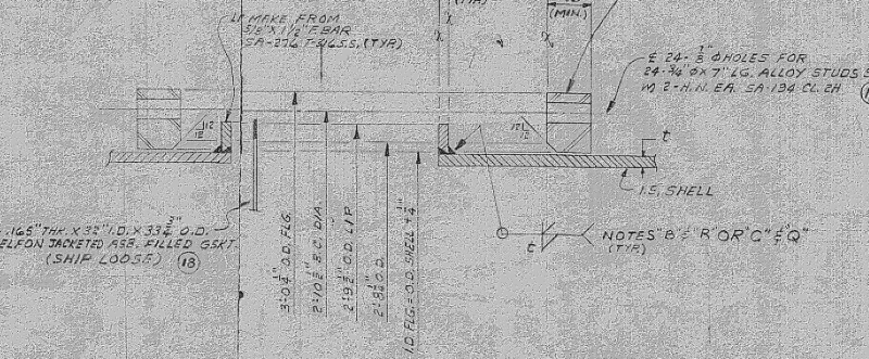
I am working on a COMPRESS model for a vertical trayed tower/vessel for a customer that wants to know if it can take Full Vacuum, or alternatively what the MAEP would be. The tower is from 1963 and includes two sets of body flanges that are lap joint design (with the lap being a weld on as shown in Figure 2-4, 1(a)). I've been digging into UG-28 in Section VIII and manipulating my model, and I've yet to have COMPRESS recognize these types of flanges as a line of support. I don't believe that this flange design can be treated as a line of support when compared something like a weld neck body flange. Overall question, can anyone confirm my line of thinking?


lapjoint flanges come in many varities, you'll need to be specific about the flanged nozzles involved, then the vessel experts can help you
 
LiewehrW, I'd say if your lap rings can be shown to meet UG-29 they may be treated as lines of support, if not, then not.

This is not necessarily the same thing as convincing your software that it is so.

Regards,

Mike

The problem with sloppy work is that the supply FAR EXCEEDS the demand
 
To help visualize the flanges in question, I have a snippet from the tower print.

Capture_tm90pi.png
 
You would not be able to count on the beneficial effects of friction, therefore I would think you would be limited to the strength of the stub end to stiffen the shell.
 
BJI said:
...beneficial effects of friction...

Care to explain this statement?

The problem with sloppy work is that the supply FAR EXCEEDS the demand
 
Since it is a lap flange, to transfer load from the shell to the ring, it must be by friction through the interface between the stub end and the backing flange. It may be a high load but given that there is high flange rotation (closer to line contact at edge of stub) and general thermal cycling, I would not rely on this connection to develop compressive hoop stress in the ring. The stub end is welded, provided it is suitable for the loads you could count this as a line of support for buckling. It might be a conservative approach but I can calculate it as a stiffener if required.
 
BJI, yes, I am sure Code recognizes no continuity between a loose flange and the lap ring. Based on the definition of L, UG-28(b), I believe the lap ring must meet the requirements of UG-29 to be considered a line of support.

The problem with sloppy work is that the supply FAR EXCEEDS the demand
 
Status
Not open for further replies.

Part and Inventory Search

Sponsor

Back
Top