Oaklandishh,
I'd recommend an approach that more closely matches the imaginary assembly you describe. Here's a possibility:
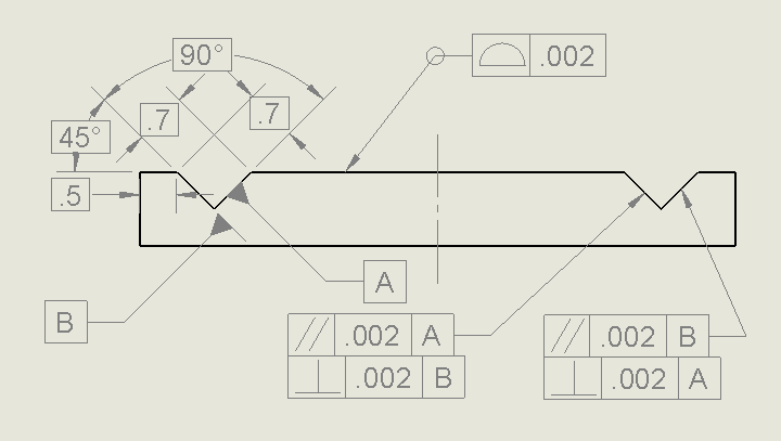
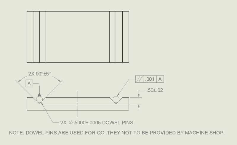
In the end view, use phantom lines to show one of the imaginary cylinders as a circle tangent to the flat surfaces of the V-groove. Attach a datum target symbol to the circle. Specify the basic diameter of the cylinder in the top half of the symbol, and assign an identifier (I'll use "A1" for this example) in the bottom half.* This will establish a datum axis that can be used to constrain two translational and (more importantly) two rotational degrees of freedom.
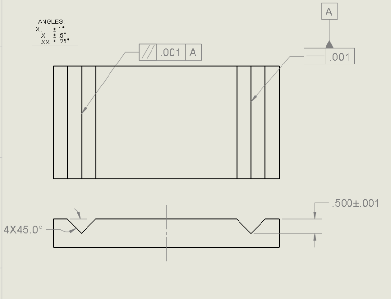
To control relationship of the second V-groove to datum axis A, you have some options. A standard method would be to apply a parallelism tolerance (referencing datum A) to each of the flat surfaces, or better yet, to a small portion of each surface that will include the contact line.
Alternately, you could show the second cylinder as a circle just like the first, give it a basic diameter dimension, and apply a parallelism tolerance referencing datum A to create a cylindrical tolerance zone of the required diameter. Applying a parallelism tolerance to an imaginary cylinder isn't exactly standard-compliant, so you should probably explain the intention with a note.
*For a related example, see datum target A2 in Fig. 4-49 of ASME Y14.5-2009.
pylfrm