Continue to Site

Eng-Tips is the largest engineering community on the Internet

Intelligent Work Forums for Engineering Professionals

  • Congratulations waross on being selected by the Eng-Tips community for having the most helpful posts in the forums last week. Way to Go!

Joist Extension Correction RFI

Status
Not open for further replies.

oengineer

Structural
Apr 25, 2011
732
I have an RFI that I need some help on. Here is the RFI:

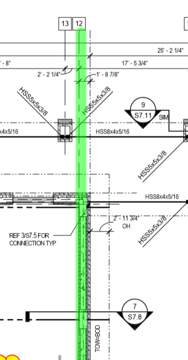
"Contractor has identified an issue where the Gym joists that rest on the wall along gridline 12 have an incorrect chord extension due to an error by the joist manufacturer. As fabricated these joists' top chords only extend 2'-11 3/4" from the outside face of the wall, wheras they should extend 3'-4 7/8". They are correcting the issue and designing for joist extensions but need the following questions answered to do this:Can you provide us the actual DL and LL that the joist extensions need to be designed for? I am having trouble getting a section to work using the 1000 plf load that is shown on the main span."

Here is the plan view:
 
Replies continue below

Recommended for you

Any suggestions on how to proceed are appreciated.
 
You could provide them with the actual DL and LL that the joist extension needs to be designed for.
 
What joist spacing do you have? 1000 plf seems to indicate you have a 20' joist spacing w/ a roof LL of 20 psf and DL of 30 psf.
 
I would be surprised if they can't make the cantilever work. They designed it for 3 feet and it needs to be 3'-5"? That's a 30% increase, but the moment is just 6 foot-kips.

If your load is really 1000 plf (that's a big load for a semi-std joist) then their engineer will need to figure out how to make it work. Weld some angles from the first panel point to the end of the cantilever or whatever.

If you gave them factored loads and they think they are service loads, that would make the problem go away.
 
Plan said:
JOIST ENGINEER TO DESIGN SCISSOR JOISTS FOR:
-ROOF LIVE LOAD OF 400 PLF
-ROOF DEAD LOAD OF 600 PLF
-TOTAL ROOF LOAD OF 1000 PLF (CONTRACTOR TO COORDINATE ADD'L LOADING DUE TO BASKETBALL GOALS W/JOIST ENGINEER

The requested information is included on the drawing (see above). The last sentence would not apply to joist extensions as the Basketball goals are inside the building. There may be an additional load for a fascia at the end of the joist and the exterior soffit may be different in weight than the ceiling inside.

It seems strange that a five inch difference in cantilever length would pose a problem.

BA
 
@BAretired
I am new to this indstry, but should there be an explicit joist extensions DL & LL to design scissor joist for? Or is it as simple as designing the extensions for Roof Live Load of 20 psf as stated in ASCE 7? What is the process in designing joist extensions? I see we have ROOF LIVE LOAD OF 400 PLF and ROOF DEAD LOAD OF 600 PLF. Should the joist engineer just use that to design the joist extensions?

@Rabbit12
18.25 ft is the max spacing of the joist.

@Once20036
Would this just be LL = 20 psf as stated in ASCE 7? For the dead load, we typically use 25 psf.
 
OP said:
I am new to this indstry, but should there be an explicit joist extensions DL & LL to design scissor joist for?
Only if it differs from the load on the span.

OP said:
Or is it as simple as designing the extensions for Roof Live Load of 20 psf as stated in ASCE 7?
That would be wrong! Your drawing stipulates LL = 400 psf which is equivalent to 22 psf. The joist designer cannot make an assumption contrary to what you have specified.

OP said:
What is the process in designing joist extensions?
The process is to design the joist extension for the specified load. If L is the length of cantilever, M = w*L2/2. Your drawing shows the end of joist to be 2'-11 3/4" from the outside face of wall. This is not good structural dimensioning; better to provide a dimension to Gridline 12. In any event, the RFI is not correct when it says: As fabricated these joists' top chords only extend 2'-11 3/4" from the outside face of the wall, wheras they should extend 3'-4 7/8".
The contractor seems to be indicating the outside face of bearing wall, not the outside face of brick veneer. In any case, the difference in length is small and should not be difficult to remedy.
ScissorJoist_gkxagn.png


OP said:
I see we have ROOF LIVE LOAD OF 400 PLF and ROOF DEAD LOAD OF 600 PLF. Should the joist engineer just use that to design the joist extensions?
Yes, he/she should have used the specified loads.

BA
 
@BAretired

Would it be possible to use a live load reduction for the joist extension design?

From your previous post it seems that 1000 plf is the incorrect value to use for the joist extension design, but based on the live & dead loads shown it adds up. I did not personally place the 1000 plf on the drawing, so does 1000 plf seem excessive?
 
@Once20036
Would this just be LL = 20 psf as stated in ASCE 7? For the dead load, we typically use 25 psf.

Of course it is possible to use a live load reduction if you are satisfied that it is justified. At present, you have specified 400 plf for joists spaced at 54.75/3 = 18.25', so your drawing specifies a live load equivalent to 21.9 psf for the purpose of joist design. I don't know where the building is located so cannot comment on your choice of live load. It should be in your code.

I have never suggested that 1000 plf is incorrect. Where the heck did you get that idea? In my neck of the woods, we get lots of snow, so live load would be substantially greater here than it is there.

As for the dead load, you need to study the architectural drawings to find out what kind of roofing has been specified. Your comment to Once20036 above states that you typically use 25 psf.

I don't typically use any particular value because it can vary depending on deck weight, mechanical/electrical allowance and the architectural roofing and ceiling specifications.
If you typically use 20 + 25 LL + DL, then typically, the total load per joist would be 45(18.25) = 821 plf in this case. I am in no position to comment on the adequacy of that load.

BA
 
@BAretired

I will have to look at the general notes section to see if it mentions something else (my computer crashed while I was looking at the actual plan sheets). Would it be typical to use an increased DL for gym roofs or for using scissor joist?
 
I have never used acoustical metal deck with a span of 18'-4" and could not find load tables for it but that may be a bit heavier than typical steel deck. I am not aware of increased DL for gym roofs or for using scissor joists but your general notes may cover design loads.

BA
 
@BAretired

The following information is provided in the general notes section of the plans. I believe the 1st 5 notes are the most applicable to this situation:

1.)ALL ROOF FRAMING TOP CHORD EXTENSIONS OF STEEL JOIST SHALL BE DESIGNED BY THE JOIST ENGINEER FOR 45 PSF TOTAL, 20 PSF LIVE
UNIFORM GRAVITY LOADING, AND 75 PSF WIND UPLIFT (TYPICAL ALL TOP CHORD EXTENSIONS UNO).

2.)JOIST ENGINEER SHALL DESIGN AND PROVIDE JOIST SYSTEMS WITH CANTILEVERED “JOIST SUBSTITUTE” JOISTS FOR ALL CONDITIONS SHOWN ON
THE FRAMING PLANS, EVEN IF THE BACKSPAN LENGTHS ARE LESS THAN THE UNSUPPORTED CANTILEVERED LENGTHS AND EVEN IF THERE IS A
DEVIATION FROM SJI DEFAULT STANDARDS. THE CONTRACTOR SHALL INCLUDE ALL COSTS ASSOCIATED WITH THIS REQUIREMENT IN THE
PROPOSAL. THE JOIST ENGINEER SHALL DETERMINE THE REACTIONS AT JOIST SUBSTITUTE JOISTS SUPPORT POINTS AND PROVIDE SUFFICIENT
VERTICAL RESISTANCE (UP AND DOWN) IN JOIST CONNECTIONS AND IN OTHER JOIST MEMBERS THAT SUPPORT JOIST SUBSTITUTE JOISTS.

3.)ROOF JOIST SUPPORTING ROOFTOP MECHANICAL EQUIPMENT (RTU'S OR OTHERWISE) SHALL BE DESIGNED BY THE JOIST ENGINEER TO SUPPORT
THE INDICATED ADD-LOADS, AS DEFINED IN THE SJI CODE OF STANDARD PRACTICE FOR STEEL JOIST AND JOIST GIRDERS, PLUS A UNIFORM LOAD OF
45 PSF TOTAL LOAD (20 PSF LIVE LOAD). THE MAXIMUM DEFLECTION OF ANY ROOF JOIST SHALL BE L/240 UNDER TOTAL LOAD AND L/360 UNDER LIVE
LOAD. LOADINGS FOR MECHANICAL EQUIPMENT ARE BASED ON THE UNIT(S) SHOWN ON THE STRUCTURAL DRAWINGS. ANY CHANGES IN TYPE, SIZE,
WEIGHT OR NUMBER OF UNIT(S) SHALL BE REPORTED TO THE ARCHITECT PRIOR TO FABRICATION OR INSTALLATION OF STRUCTURAL MEMBERS OR
MECHANICAL EQUIPMENT.

4.)UNLESS INDICATED OTHERWISE ON THE DRAWINGS, WHERE JOISTS ARE SUPPORTING WALL LOADING, THE ADDITIONAL LOAD THE JOISTS ARE
REQUIRED TO SUPPORT SHALL BE DETERMNED BY THE JOIST ENGINEER BASED ON THE FOLOWING ASSUMED WALL LOADING:
A. MASONRY VENEER: 39 PSF X HEIGHT OF WALL SUPPORTED
B. CFMF WALL: 12 PSF X HEIGHT OF WALL SUPPORTED
C. CMU WALL: 75 PSF X HEIGHT OF WALL SUPPORTED

5.)THE JOIST GIRDERS SHALL BE DESIGNED AS A SIMPLE SPAN WITH THE UNFACTORED JOIST REACTIONS INDICATED BY THE JOIST GIRDER
DESIGNATION (DEAD LOAD AND LIVE LOAD).

STEEL JOISTS SHALL CONFORM TO THE REQUIREMENTS OF THE STEEL JOIST INSTITUTE STANDARD SPECIFICATIONS FOR OPEN WEB JOISTS.
MATERIAL SHALL BE DOMESTIC STEEL WITH ANGLES FOR BOTTOM CHORDS. BRIDGING SHALL BE PROVIDED FOR ALL JOISTS IN ACCORDANCE WITH
SJI REQUIREMENTS.

METAL ROOF DECK SHALL BE PROVIDED IN ACCORDANCE WITH THE PROJECT SPECIFICATIONS AND AS INDICATED ON THE PLANS. METAL ROOF DECK
SHALL BE ATTACHED TO SUPPORTING MEMBERS PER THE PROJECT SPECIFICATIONS.

ALL JOISTS SHALL HAVE BOTTOM CHORD UPLIFT BRIDGING AT EACH END AND BE DESIGNED FOR 35 POUNDS PER SQUARE FOOT NET UPLIFT.

FOR ALL ROOF PENETRATIONS THROUGH METAL DECK 8” OR LARGER PROVIDE AN L3X3X1/4 AROUND THE OPENING AND FRAME ALL SIDES (EXCEPT
WHERE OPENING EDGE IS WITHIN 1'-0” OF ANOTHER FRAMING MEMBER - JOIST/BEAM) WITH A STRUCTURAL MEMBER. FRAMING NOT REQUIRED FOR
ROOF OPENINGS SMALLER THAN 8”.

THE ROOF DECK IS STANDING SEAM AND WILL NOT BRACE THE TOP CHORD OF THE BAR JOISTS. EXTRA BRIDGING IS SHOWN ON THE PLAN, BUT THE
JOIST MANUFACTURER IS RESPONSIBLE FOR VERIFYING BRIDGING SPACING AND DESIGNING THE TOP CHORD AS REQUIRED FOR THE BRACING
SPACING.

LOCATE CONCENTRATED LOADS ON JOISTS AT PANEL POINTS. PROVIDE ANGLE WEB MEMBERS TO CREATE INTERMEDIATE PANEL POINTS AS
REQUIRED. MANUFACTURER SHALL DIRECT INSTALLER AS TO METHOD OF INSTALLATION AND MATERIAL REQUIRED. JOISTS AND JOIST GIRDERS
SHALL BE SHOP REINFORCED FOR ALL LOADS PROVIDED ON DRAWINGS. FIELD REINFORCING SHALL BE PROVIDED AS DETAILED ON THE DRAWINGS.

METAL ROOF DECK IS DESIGNED FOR 3 SPAN CONDITIONS. IT IS THE RESPONSIBILITY OF THE DECK SUPPLIER TO ADJUST THE THICKNESS (GAUGE)
OF THE ROOF DECK AT SINGLE OR DOUBLE SPAN CONDITIONS AS REQUIRED BY THE STEEL DECK INSTITUTE.

PROVIDE SUPPORT FOR EDGES OF DECK WHETHER SHOWN ON THE DRAWINGS OR NOT.

UNLESS INDICATED OTHERWISE ON THE DRAWINGS, WHERE BRACES ARE SHOWN TO ATTACH TO THE ROOF JOIST, THE ENGINEER SHALL ASSUME
THE LOAD IN AXIAL LOAD IS EQUAL TO A COMPRESSION OR TENSION SERVICE LEVEL WIND LOAD OF 2 KIP.
 

OP's Gen Notes said:
1.)ALL ROOF FRAMING TOP CHORD EXTENSIONS OF STEEL JOIST SHALL BE DESIGNED BY THE JOIST ENGINEER FOR 45 PSF TOTAL, 20 PSF LIVE UNIFORM GRAVITY LOADING, AND 75 PSF WIND UPLIFT (TYPICAL ALL TOP CHORD EXTENSIONS UNO).

Looks like wind uplift is the most critical loading for the top chord extensions. Net uplift is 75 - 25 = 50 psf.

OP's Gen Notes said:
ALL JOISTS SHALL HAVE BOTTOM CHORD UPLIFT BRIDGING AT EACH END AND BE DESIGNED FOR 35 POUNDS PER SQUARE FOOT NET UPLIFT.
So total wind uplift = 35 + 25 = 60 psf. This means that the bottom chords will need bracing as they will be in compression. Again, wind is the governing load.

OP's Gen Notes said:
THE ROOF DECK IS STANDING SEAM AND WILL NOT BRACE THE TOP CHORD OF THE BAR JOISTS. EXTRA BRIDGING IS SHOWN ON THE PLAN, BUT THE JOIST MANUFACTURER IS RESPONSIBLE FOR VERIFYING BRIDGING SPACING AND DESIGNING THE TOP CHORD AS REQUIRED FOR THE BRACING SPACING.
Top and bottom chords can be in compression, but not at the same time. Neither can be considered braced. Bridging is going to be very important and a little unusual.

BA
 
@BAretired

It appears the joist designer did not consider the wind load when designing the joist extensions.

At this point, I want to tell the joist manufacturer that:

ALL ROOF FRAMING TOP CHORD EXTENSIONS OF STEEL JOIST SHALL BE DESIGNED BY THE JOIST ENGINEER FOR 45 PSF TOTAL, 20 PSF LIVE UNIFORM GRAVITY LOADING, AND 75 PSF WIND UPLIFT (TYPICAL ALL TOP CHORD EXTENSIONS UNO).

OR

Use LL = 400/18.33 = 22 psf & DL = 600/18.33 = 33 psf for the joist extension design.
 
@JLNJ

Based on the notes and load values shown, these appear to be service loads.

1.2*25 +1.6*20 = 62 psf total, if it was factored.

@BAretired

Please let me know if you agree with my response.
 
oengineer said:
It appears the joist designer did not consider the wind load when designing the joist extensions.

At this point, I want to tell the joist manufacturer that:

ALL ROOF FRAMING TOP CHORD EXTENSIONS OF STEEL JOIST SHALL BE DESIGNED BY THE JOIST ENGINEER FOR 45 PSF TOTAL, 20 PSF LIVE UNIFORM GRAVITY LOADING, AND 75 PSF WIND UPLIFT (TYPICAL ALL TOP CHORD EXTENSIONS UNO). (See General Notes, Note 1.)

OR

Use LL = 400/18.33 = 22 psf & DL = 600/18.33 = 33 psf for the joist extension design.
Add the text in blue. Don't give him the text in red. Let him figure it out. Your 400 + 600 plf allows for some slight difference in deck reactions due to continuity.


BA
 
Can't argue with Celt83 on that point. I sort of assumed that the engineer who stamped the drawings is no longer available. If that is the case, it would still be a good idea to discuss the matter with other engineers in your office.

BA
 
@BAretired & Celt83

My goal is to coordinate a response with the E.O.R. now that I have made an attemp to determine the loads. The E.O.R. is still available.
 
Status
Not open for further replies.

Part and Inventory Search

Sponsor