Continue to Site

Eng-Tips is the largest engineering community on the Internet

Intelligent Work Forums for Engineering Professionals

  • Congratulations The Obturator on being selected by the Eng-Tips community for having the most helpful posts in the forums last week. Way to Go!

ISO 8062 and ISO 2768 for one dimension

MaciejM

Automotive
May 21, 2025
2
Hi everyone,

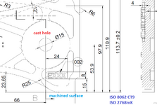
I have a drawing of a cast plate, and on this drawings there is a dimension for both cast and machined features. I want measure this 53,9 distance from a cast hole to a machined face. Should I add tolerances CT9 (±1) from ISO 8062 and from ISO 2768mK (±0,3), or just stick to CT9?
 

Attachments

  • Cast.png
    Cast.png
    97 KB · Views: 16
Replies continue below

Recommended for you

What is CT9? Is it a tolerance grade? Your machined surface seems too small to locate the hole, or vice versa.
 
Why do you want to use any of these redundant standards?
Just apply the tolerances that will make it work.
What are the functional considerations?
Does the flat surface locate the part in the vertical direction or the hole? The one that does should be a datum feature of some order, probably not the primary bacause they both are too small to orient the part. Choose a datum reference frame that makes sense for constraining all relevant degrees of freedom. The distance dimension should be basic. Then if the hole is controlled from the flat end use position, or if the flat end is controlled from the hole use profile. Maybe they both should be dimensioned and controlled relative to something else and then none of them is a datum feature. Their distance from each other would result from both their location tolerances. Assign the tolerance values as wide as your design can tolerate. Good luck, and get rid of those silly general +/- standards.
 
Last edited:
Why do you want to use any of these redundant standards?
Just apply the tolerances that will make it work.
What are the functional considerations?
Does the flat surface locate the part in the vertical direction or the hole? The one that does should be a datum feature of some order, probably not the primary bacause they both are too small to orient the part. Choose a datum reference frame that makes sense for constraining all relevant degrees of freedom. The distance dimension should be basic. Then if the hole is controlled from the flat end use position, or if the flat end is controlled from the hole use profile. Maybe they both should be dimensioned and controlled relative to something else and then none of them is a datum feature. Their distance from each other would result from both their location tolerances. Assign the tolerance values as wide as your design can tolerate. Good luck, and get rid of those silly general +/- standards.
Both standards specifies general tolerances for linear dimensions, when they are not explicitly stated on technical drawings. As you see there is no tolerance on 53,9 dimension. So in that case we have to take this tolerance from one of those two norms. But:
- it is a cast part, and it's define as ISO8062 CT9 so for 53,9±1
- it is a cast part where one surfece is milled, and I'm not covinced whether I can use ISO8062 norm because for this purpose we have ISO2768 standard (in this case on drawing is ISO2768mK).
That is why I try to find someone with experience in cast part. This is not my drawing, I need measure it but I don't know what tolerance should I use.
 
Just measure it and leave the "Accept/Reject" and tolerance entries blank, or use both tolerances on the inspection report and put on separate Accept/Reject choices for both of them. If they are both "Accept" or both "Reject" it won't matter which applies. If one is "Accept" and the other "Reject" then call the customer and tell them that the part will be put on a shelf until that is clarified.
 
Both standards specifies general tolerances for linear dimensions, when they are not explicitly stated on technical drawings. As you see there is no tolerance on 53,9 dimension. So in that case we have to take this tolerance from one of those two norms. But:
- it is a cast part, and it's define as ISO8062 CT9 so for 53,9±1
- it is a cast part where one surfece is milled, and I'm not covinced whether I can use ISO8062 norm because for this purpose we have ISO2768 standard (in this case on drawing is ISO2768mK).
That is why I try to find someone with experience in cast part. This is not my drawing, I need measure it but I don't know what tolerance should I use.
Ok, now that clarifies the intent of the question. I think 3DDave offered a solution that makes perfect sense starting from his second sentence.
 

Part and Inventory Search

Sponsor