Continue to Site

Eng-Tips is the largest engineering community on the Internet

Intelligent Work Forums for Engineering Professionals

  • Congratulations cowski on being selected by the Eng-Tips community for having the most helpful posts in the forums last week. Way to Go!

Is a position tolerance on two opposed edges valid?

Status
Not open for further replies.

JBATX

Mechanical
Aug 18, 2016
8
position_of_two_edges_co2wh1.png

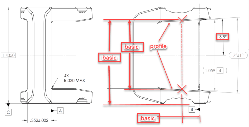
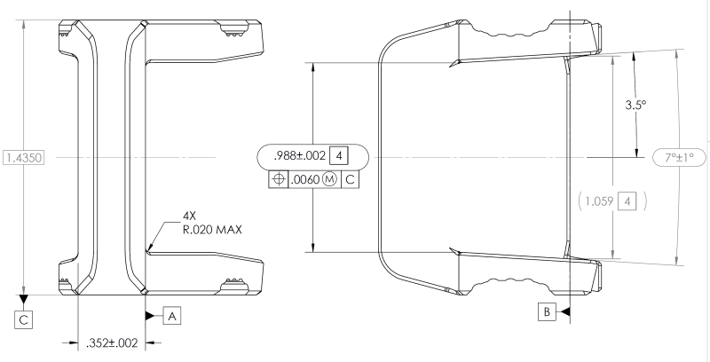
I came across this callout on a drawing I was asked to review. I'm pretty sure the position tolerance on the two opposed edges is not a valid callout and I think I understand how to explain why but wanted to confirm my thinking with some of the experts here. Ignoring the fact that the edges aren't really there on the physical part as they are a theoretical intersection (flag 4) my understanding is that this feature cannot be considered an irregular feature of size as you cannot create an AME. Two parallel planes expanding to the edges would not be constrained in orientation. They could vary up to the angle of the surfaces.
I don't really like how these features are dimensioned altogether but that particular callout has me thinking it has to change to be valid to the standard (we currently use ASME Y14.5-2009). My suggestion would be to use surface profile, potentially a composite profile if some additional location allowance is desired.
 
Replies continue below

Recommended for you

Not valid. FOS requires parallel faces.

Also, there's no way they can reliably grab that tangency they are measuring from.
 
I also agree the dimension .988 is not related to a feature of size, and therefore the position tolerance is a problem.

The only reasonable counterargument you might get has to do with the fact that the position tolerance is specified on an MMC basis, and the surface interpretation of it allows for use of a fixed size gage .980 wide representing a boundary not to be violated.
So while the "legality" is questionable at best, interpretation feasibility and inspectability is there, assuming there is a reliable way to inspect the "size" tolerance of +/-.002.
 
So how did you end up resolving this?
Were the directly toleranced distance and angles replaced by basic dimensions and profile of a surface tolerance?
 
Define the plane/line using basic dimensions and control with a profile. The line is defined by a point and angle. The point is defined by basic dimensions from datums.
2022-05-03_13-14-06_xowul6.png
 
Status
Not open for further replies.

Part and Inventory Search

Sponsor