Tek-Tips is the largest IT community on the Internet today!

Members share and learn making Tek-Tips Forums the best source of peer-reviewed technical information on the Internet!

  • Congratulations JStephen on being selected by the Eng-Tips community for having the most helpful posts in the forums last week. Way to Go!

Interpretation of CSA S16 Cl 16.5.6.2

EngDM

Structural
Joined
Aug 10, 2021
Messages
811
Location
CA
Hi all,

I am wondering what the accepted way to interpret this clause regarding joist top chords is. I have spoken with reps from different joist manufacturers where they all said that they take the value of Lz as zero (or 1mm to make it not govern) for B2B angle top chords, typically with a gap of 1" between pieces. It was explained to me that the way the Lz fails is by flattening the angle out along it's skew axis and the deck restrains it. That being said, S16 appears to directly prohibit doing this.
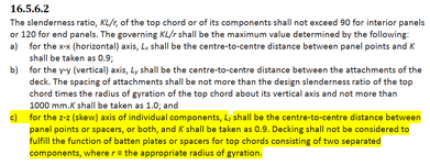
16.5.6.2.png

Subsequently, for shapes where the principle axes are the same as the axes by which the joist is loaded, such as a hat channel or an omega joist, does this imply that there is no skew angle and the Lz check can be omitted? (Angles are listed in the table with axes parallel to the legs, as well as the principle axes. The way by which angles bend is outlined in this article by Graitec)

When I run a calculation for compressive resistance of a hat channel joist, there is a large difference in strength when I put in Lz as my panel point spacing, vs taking it as non-governing since there is no skew axis. I just want to make sure I'm not being unconservative by ignoring the Lz.
 
Last edited:
Singly or doubly symmetric sections would not have a skew angle so no Lz check. I read it the same as you but can't say I've dived too deep into the OWSJ space. I suspect this is a new addition to the code (well, since 2014 which is my hard copy) that hasn't percolated through the manufacturers yet.
 
It was explained to me that the way the Lz fails is by flattening the angle out along it's skew axis and the deck restrains it.

I can certainly see how that logic could be deemed to be flawed, particularly given that the fasteners are likely the weak link.

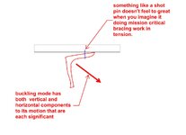
The deck will increase capacity some amount relative to there being no deck but then you'll likely just be left with some marginally better and extremely difficult to evaluate constrained component version of the Lz buckling mode to deal with. It's similar to how some folks check WF beam diaphragm chords using the weak axis check rather than the torsional check when the top flange is laterally restrained by the deck.

The other thing to consider is the amount of bracing strength and stiffness that will be required for the deck to perform the bracing function. The angles forming sine waves between the panel points / spacers will already kick the axial capacity up pretty high relative to the squash load of the chords. Kicking it up even further to the small distance between deck fasteners may require some big bracing capacities.

In practice, I'm sure that resolving this probably just comes down to adding a few extra spacers.


01.JPG
 
Singly or doubly symmetric sections would not have a skew angle so no Lz check. I read it the same as you but can't say I've dived too deep into the OWSJ space. I suspect this is a new addition to the code (well, since 2014 which is my hard copy) that hasn't percolated through the manufacturers yet.
It's in S16-14 and I believe S16-09, which is why I am surprised that I have been given a justification from manufacturers when it is a code requirement. Perhaps they have done in-house testing that shows even the lightest of roof assemblies will restrain the chord adequately for Lz failure.

I can certainly see how that logic could be deemed to be flawed, particularly given that the fasteners are likely the weak link.

The deck will increase capacity some amount relative to there being no deck but then you'll likely just be left with some marginally better and extremely difficult to evaluate constrained component version of the Lz buckling mode to deal with. It's similar to how some folks check WF beam diaphragm chords using the weak axis check rather than the torsional check when the top flange is laterally restrained by the deck.

The other thing to consider is the amount of bracing strength and stiffness that will be required for the deck to perform the bracing function. The angles forming sine waves between the panel points / spacers will already kick the axial capacity up pretty high relative to the squash load of the chords. Kicking it up even further to the small distance between deck fasteners may require some big bracing capacities.

In practice, I'm sure that resolving this probably just comes down to adding a few extra spacers.


View attachment 15643
I always appreciate the sketches, helps put a visual to the words for stuff I can't quite picture myself, especially in stuff that I am unsure about.
 

Part and Inventory Search

Sponsor

Back
Top