Continue to Site

Eng-Tips is the largest engineering community on the Internet

Intelligent Work Forums for Engineering Professionals

  • Congratulations cowski on being selected by the Eng-Tips community for having the most helpful posts in the forums last week. Way to Go!

Inner/Outer Boundary Method

Status
Not open for further replies.

pyromech

Mechanical
Jul 30, 2008
39
I came across IB/OB boundary method for calculating stacks. See image. It looks simple but i just not getting the right answer when it comes to the axis perpendicularity control. The problem might be the bonus tolerance which i neglect because i thought it doesnt get one. Please explain what i am missing

thank you

Boundary-Stack_bmyy3x.png


Replies continue below

Recommended for you

I have attached my stack calculation. Please note that I only did the scenario where the pin is pushed to the far left, which results in the overall minimum value of -.35 units. The calculated max value for this scenario (3.05 units) is not the overall max. You would need to redo this calculation with the pin pushed to the far right to calculate the overall maximum value.
 
 http://files.engineering.com/getfile.aspx?folder=43309ed9-6b4b-4818-bf95-0d320e74f343&file=stack_for_formum_min_only.pdf
pyromech,

Do you agree with the calculated values shown: IB and OB?

If not, I guess you have to reconcile these numbers first.
Then use only resultant condition for the plug (smaller OD) = 5.6 and the resultant condition for the sleeve ID= 8.7 to get the worst case of 3.1 used in the evaluation.
3.1 value is used in both evaluations for minimum and also for the maximum.

 
aniiben said:
Do you agree with the calculated values shown: IB and OB?

I still dont understand the datum shifts that joint #1 plays into. But I broke it down separately for me to comprehend. Though I appreciate everyone input. Something like this:

+8.2 +7.8 Sleeve diameter
-0.1 Perp control Tol​
+0.5 (8.2-7.8)+ Perp control Tol
-5.9 -6.1 Pin diameter
-0.1 Perp control Tol​
+0.3 (6.1-5.9) + Perp control Tol

=+3.1 +1.5

 
pyromech,

I think the most difficult part in trying to understand the calculations shown in the book is to realize that the numbers:
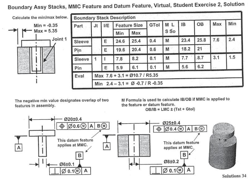
IB = 7.7, OB = 8.7 for sleeve datum feature B,
IB = 5.6, OB = 6.2 for pin datum feature B,
Max = 3.1, Min = 1.5
have been quite cleverly used to simultaneously simulate two different things:

1. A possible physical loose between datum features B of both parts in the assembly.
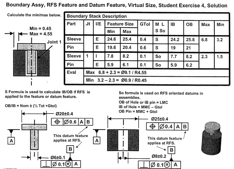
For the stack-up objectives only maximum loose needs to be considered. The maximum loose will take place when the datum feature B of the pin has been produced perfectly perpendicular to A and at LMC size = 5.9, and the datum feature B of the sleeve has been also produced perfectly perpendicular to A and at LMC size = 8.2. This gives maximum possible loose between both datum features B of 2.3 (8.2-5.9). But that is 0.8 less than 3.1! And here another thing comes into play.

2. A possible physical loose between datum feature simulator B and datum feature B for each part individually (even before parts get assembled together).
- for pin, fixed size of datum feature B simulator is 6.2. So the maximum amount of loose between the simulator and the datum feature is 0.3 (6.2-5.9).
- for sleeve, fixed size of datum feature B simulator is 7.7. So the maximum amount of loose between the simulator and the datum feature is 0.5 (8.2-7.7).
- 0.3 plus 0.5 gives lacking 0.8.

Side note: I would really like to see how (if) the book shows similar stack-up but with both position callouts referencing to |A|B| (no MMB modifier for B). It would be interesting to see how the author got different end results comparing to the original example without changing IB and OB sizes of both datum features B.
 
pmarc said:
Side note: I would really like to see how (if) the book shows similar stack-up but with both position callouts referencing to |A|B| (no MMB modifier for B)
See below.
EX36_u8qwbn.png


This example is pretty straightforward.

+8.2 +7.8 Sleeve Dia
-0.1 Perp Control​
-5.9 -6.1 Pin Dia
-0.1 Perp Control​

I like to interpret gd&t in practical ways so my understanding is that at MMC, Perpendicularity control works the opposite of bonus tolerance where the latter is applied when the feature is at LMC. So in this example, Perp is applied when feature is at MMC. therefore, 0.1 is applied when sleeve hole is at MMC (7.8) or pin at MMC (6.1)

But what would happen if there is no M modifier on the Perp control for this example and the first example. ??? Will the 0.1 Perp Tolerance apply at all?
 
pyromech,

Thank you for attaching the second example.

I too like to interpret GD&T in practical ways, that is why I have to say I don't like the methodology presented on both illustrations. One problem is that this approach works only if some rigid formulas for OB and IB are used. And the other thing is that these formulas lead to results that in some places are illogical from GD&T point of view (at least to me).

For example, why aren't all 4 values of OBs and IBs of datum features B the same in both cases? (Actually, I believe I know why - with that approach taken in order to get to correct answer the author needs to arbitrarily (through formulas) modify IB size of pin datum feature B and OB size of sleeve datum feature B). If both datum features B are controlled in exactly the same way for size and orientation to respective datum planes A, shouldn't their IB and OB sizes be the same in both cases?
 
Status
Not open for further replies.

Part and Inventory Search

Sponsor