pyromech,
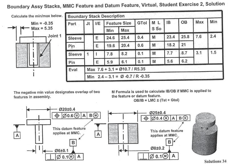
I think the most difficult part in trying to understand the calculations shown in the book is to realize that the numbers:
IB = 7.7, OB = 8.7 for sleeve datum feature B,
IB = 5.6, OB = 6.2 for pin datum feature B,
Max = 3.1, Min = 1.5
have been quite cleverly used to simultaneously simulate two different things:
1. A possible physical loose between datum features B of both parts in the assembly.
For the stack-up objectives only maximum loose needs to be considered. The maximum loose will take place when the datum feature B of the pin has been produced perfectly perpendicular to A and at LMC size = 5.9, and the datum feature B of the sleeve has been also produced perfectly perpendicular to A and at LMC size = 8.2. This gives maximum possible loose between both datum features B of 2.3 (8.2-5.9). But that is 0.8 less than 3.1! And here another thing comes into play.
2. A possible physical loose between datum feature simulator B and datum feature B for each part individually (even before parts get assembled together).
- for pin, fixed size of datum feature B simulator is 6.2. So the maximum amount of loose between the simulator and the datum feature is 0.3 (6.2-5.9).
- for sleeve, fixed size of datum feature B simulator is 7.7. So the maximum amount of loose between the simulator and the datum feature is 0.5 (8.2-7.7).
- 0.3 plus 0.5 gives lacking 0.8.
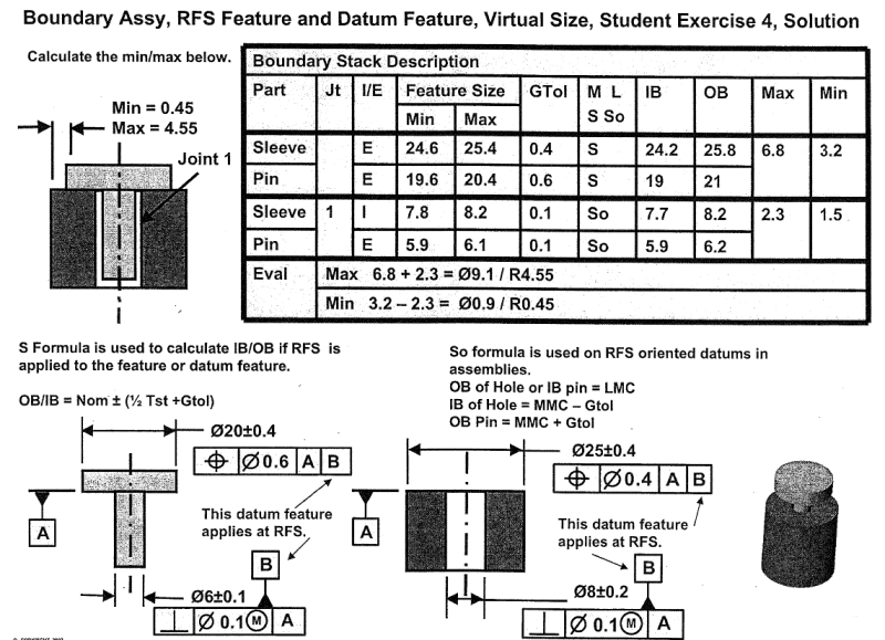
Side note: I would really like to see how (if) the book shows similar stack-up but with both position callouts referencing to |A|B| (no MMB modifier for B). It would be interesting to see how the author got different end results comparing to the original example without changing IB and OB sizes of both datum features B.


