Continue to Site

Eng-Tips is the largest engineering community on the Internet

Intelligent Work Forums for Engineering Professionals

  • Congratulations cowski on being selected by the Eng-Tips community for having the most helpful posts in the forums last week. Way to Go!

Indication of drawing scale in Solid Edge, SolidWorks, Inventor, etc... 1

Status
Not open for further replies.

sanfobr

Mechanical
Feb 21, 2008
5
Hello,

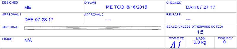
This is my first post ever, please be kind. I've been fighting a battle with my older colleges about the need to indicate scale on drawings. We design everything in 1:1 in 3D and place everything at a given scale to fit on metric A1 title block. We do not print anything full size, instead we print to 11x17 which is reduced at some odd factor. We also have noted on all our drawings "DO NOT SCALE DRAWING". I've also read several post about the issues of printing at scale accurately.

So I'm trying to make the argument that indication of scale on drawings is irrelevant and not required. I'm not arguing that scale factors be used correctly, just not indicated.

I would love to hear anyone's thoughts on this.

Thank you.

Sanfobr
 
Replies continue below

Recommended for you

Sorry Ctopher, I'm always loathed to change things related to drawing standards based on the action of one clearly inept actor.

If I were to set that precedent I'd spend all my time detailing how our company standard vary from accepted industry standards and never get anything done.

Posting guidelines faq731-376 (probably not aimed specifically at you)
What is Engineering anyway: faq1088-1484
 
All,

This has been educational to say the least. Looks like we have good arguments for and against.

I've been designing and working with engineers for the last 24 years. I'm a product of 2 years high school vocational school drafting instruction and some college. I know the standards and have played by them since day one. I work in a custom design group where every project when completed is a working prototype. Everything is fast paced and fluid. I'm never one to avoid doing the right thing out of being lazy and openly criticize those who do. Although my colleges and I within my group don't see the need for indication of scale I will most likely have to adhere to including it for our product group. We are in the process of combining the title blocks, associated macros, and internal drafting standards (referencing the current ANSI standard). There is definitely a different mindset between the two groups and it tends to get rather heated in conversation. I was hoping for a good mixture of replies so that I could share with the others and possible come to a mutual agreement.

I'd like to thank everyone for there time and comments.

Swertel, we are currently being pushed to "AUTOMATE" everything in the title block along with materials, finishes, mass, required initials, etc...The more automation is that is done the fewer user mistakes can be made is the thought here anyway. Everything we put on the drawing is CAD driven down stream.

Below I have shown the change to our title block adding the scale box back in with the disclaimer of "unless otherwise noted" (thank you JNieman, KENAT).
image_kotgb1.jpg
I fixed the image scale...how ironic! He he...

Sanfobr
Solid Edge ST7
 
While my preference would be:

A. never do business with the idiots again

I realize sometimes that's not an option in which case I'd like it to be something like:

B. Vendor has to be requalified & as much as possible work will be elsewhere.

I realize that in practice it's often:

C. Blame the engineer who did the drawing.

Posting guidelines faq731-376 (probably not aimed specifically at you)
What is Engineering anyway: faq1088-1484
 
The notation "scale ( Unless otherwise noted.)", was very often used on drawing sheets that had enlarged details on them .
For example, you would get a general scale of 1-100 with a close up detail of a part at 1-10 , or whatever the relevant scale was.
This has been around since before I started drafting ( On paper ) in 1965.
B.E.


You are judged not by what you know, but by what you can do.
 
I should also mention that some cad drafting programs have the ability of letting you change the scale of the part on the sheet as you generate the drawing from the model , so that you do not have a weird scale of 1-37.5. However there are drafters who do not know this exists or don't care.
B.E.

You are judged not by what you know, but by what you can do.
 
sanfobr,

I try very hard to draw everything 1:1, especially fabrication drawings. Most of my assemblies and arrangements are too big for 1:1, even on E[ ]size, so I select scales that are on my set of drafting scales.
[ol]
[li]We have a 36"[ ]plotter. I actually can print E[ ]sized drawings 1:1.[/li]
[li]I hang my assembly and arrangement drawings on my wall, and sometimes, I scale them. [/li]
[li]We have at least one vendor who requests full sized prints. [/li]
[li]I have a scale reference I can add to my title blocks for when exact scale really matters.[/li]
[/ol]

One of our offices which does not have an E[ ]sized plotter, has set up A[ ]sized and B[ ]sized title blocks. If you like drawing large things 1:1 or in the largest size possible, this sucks. Still, they can plot their drawings full size, and scale off them.

Does anyone here model cable harnesses in 3D[ ]CAD?

--
JHG
 
Does anyone here model cable harnesses in 3D CAD?

We've done it, but it's unusual to do it fully detailed and is becoming less common. I will model simplified representations of cable & hose routing when I need to/can justify it though.

Posting guidelines faq731-376 (probably not aimed specifically at you)
What is Engineering anyway: faq1088-1484
 
KENAT,

I suspect that our production would like us to lay out cable harness pegboards. These would have to be plotted 1:1, although extreme detail would not be necessary.

--
JHG
 
If your drawings will ever be printed on the proper size paper and have any feature measured with a scale then the view scale needs to be indicated.. If not then there is no point in having it.. plain and simple.
If its not used its not lazy to omit it.. Its more efficient as its one less thing that must be verified.

And I model all harnesses in 3D CAD using the cable/harness module of my CAD program (Inventor).
I do not do drawings for them as they are typically fairly simple and our job order routing will let the assemblers know what wire goes where in a connector. But the CAD system has "nailboard" drawing functionality too.. I just don't use it because I don't like the details of how it works.

Anxiously awaiting 3D PMI to become widely accepted and 2D drawings to die just like books have.

 
I agree that stating view scale may seem to be superfluous when full size prints are rarely used, but I think swertel makes an excellent point.
Without a quick visual indicator as to the relative scale of parts, the brain has to spend extra compute cycles "resizing" the components to make sense of how the components fit into the assembly.
A drawing should be as simple to correctly interpret as possible, and, even though it may be subtle, knowing the relative scale adds to ease of interpretation.

"Know the rules well, so you can break them effectively."
-Dalai Lama XIV
 
As long as humans are making parts at machines that don't have computers beside them, or built into them, 3D PMI will not erase the need for 2D drawings. It just means you pass the responsibility of making them on to someone else.

So yea, they will die every bit as much as books will.

Which is to say, no time in the foreseeable future.
 
Exactly.

If your company decided to produce all drawings on B or even A size, what stopping you from creating nice A or B title bock that allows good use of space and provides tiny "scale" field in the corner, especially considering that said field will usually be filled automatically?

"For every expert there is an equal and opposite expert"
Arthur C. Clarke Profiles of the future

 
3D PMI won't happen as a general solution anytime soon. To do so requires perfect round-tripping of model data among various CAD tools. There's been interest in that since CAD started, but no working examples in the last 50 years.

It's like asking Ford and Chevy to have interchangeable engines with entirely interchangeable parts. Never going to happen.

I've only looked at solving this problem for 35 years. It's a not unique to CAD; every data manipulation software has the same problem and often for the same reasons.

The only companies where it looks like it works are those where the entire supply chain is captive in some way; injection molded parts, for example, are heavily controlled by the limited number of molds, the initial precision from the mold makers, and any off-drawing discussions about tolerances. Just because it's not on the drawing, if there is one, doesn't mean the same effort isn't required. In addition, for injection molding (for example) there are very few dimensions that are critical to the part fitting, but a hugely complex description required for the decorative portions. I suspect the same is true for many lofted parts such as airframes and car bodies.
 
Status
Not open for further replies.

Part and Inventory Search

Sponsor