Perception
Structural
- Feb 4, 2015
- 34
Hello everyone,
I have a question about the formula to compute the moment capacity of a composite beam when the PNA is in the flange of the steel beam. I am perplexed by the formula given by AISC to compute moment capacity. First the stress distribution that AISC bases their formula off of is shown below.
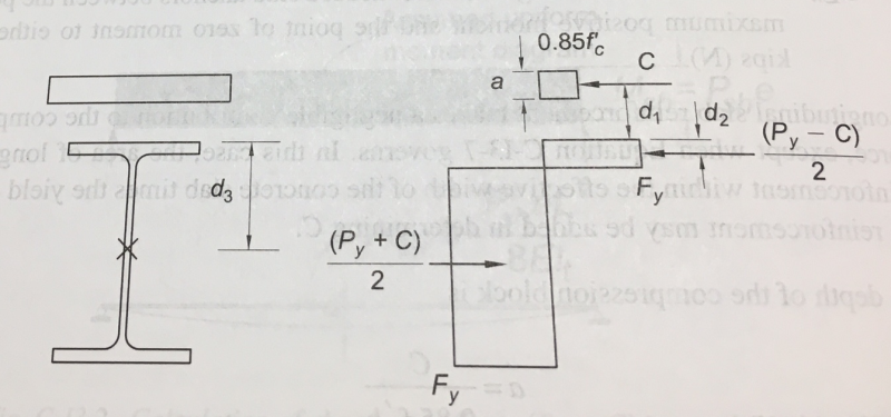
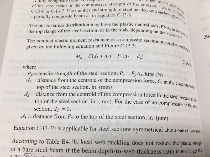
Based on the distribution above, AISC presents the formula below for the moment capacity of a composite section.
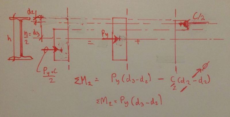
AISC is saying since both the portion of the flange in compression and the portion of the flange in tension have the term C/2 with opposite signs (see distribution above), the two terms cancel out. While this is true for the resultant force, the same logic can not be applied for summing moments. Since the two C/2 terms have different moment arms about the plastic neutral axis, the moment caused by the two terms will be different. From what I can tell steel textbooks seem to agree with this logic (at least McCormac does). I think this equation needs to be amended, or I need to refresh my statics... Am I missing something here? Is it possible that AISC decided the difference between moment arms is negligible?
I came across this discrepancy looking at the AISC Design Examples for composite section. Specifically, I was looking at example I.1 which looks at the design of a composite girder. In the example the plastic neutral axis is in the web, but the formula shown above is utilized to find the moment capacity.
A follow up question relating to the composite section moment capacities in the steel textbooks. Most of the textbooks double the compression force in the flange of the beam so they don't have to subtract anything from the tension force (i.e. T = FyAs instead of (FyAs - flange compression force) since I added more compression in the flange). I have considered both adding and not adding the additional compression in the flange, and both approaches give a different moment capacity due to the reasoning above (different moment arms). How do you choose to compute the moment capacity of a composite section when the plastic neutral axis is in the flange of the beam?
Thanks
I have a question about the formula to compute the moment capacity of a composite beam when the PNA is in the flange of the steel beam. I am perplexed by the formula given by AISC to compute moment capacity. First the stress distribution that AISC bases their formula off of is shown below.
Based on the distribution above, AISC presents the formula below for the moment capacity of a composite section.
AISC is saying since both the portion of the flange in compression and the portion of the flange in tension have the term C/2 with opposite signs (see distribution above), the two terms cancel out. While this is true for the resultant force, the same logic can not be applied for summing moments. Since the two C/2 terms have different moment arms about the plastic neutral axis, the moment caused by the two terms will be different. From what I can tell steel textbooks seem to agree with this logic (at least McCormac does). I think this equation needs to be amended, or I need to refresh my statics... Am I missing something here? Is it possible that AISC decided the difference between moment arms is negligible?
I came across this discrepancy looking at the AISC Design Examples for composite section. Specifically, I was looking at example I.1 which looks at the design of a composite girder. In the example the plastic neutral axis is in the web, but the formula shown above is utilized to find the moment capacity.
A follow up question relating to the composite section moment capacities in the steel textbooks. Most of the textbooks double the compression force in the flange of the beam so they don't have to subtract anything from the tension force (i.e. T = FyAs instead of (FyAs - flange compression force) since I added more compression in the flange). I have considered both adding and not adding the additional compression in the flange, and both approaches give a different moment capacity due to the reasoning above (different moment arms). How do you choose to compute the moment capacity of a composite section when the plastic neutral axis is in the flange of the beam?
Thanks