elfstein123
Structural
- Mar 15, 2021
- 6
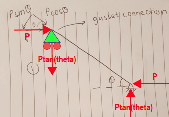
Hi everyone. I am working on a steel member design problem and wanted to clarify my thought process for calculating the member forces. The member is a brace and there is a horizontal load P on it. The brace is pinned to the floor and is connected to another member via gusset plate. The load transfer through the gusset will be P.
I originally thought that I would resolve it based on the angle of the member and get the axial and shear force on the member as shown in Option 1 on the image but that means that the member has significant moment (since we have shear and the member length) and that threw me off. I can't imagine this bending but of course buckling is possible and is checked under the axial load. Is this correct? Will we actually have moment in the member?
The second thing that popped up was to resolve it differently as shown in Option 2. We have a higher axial load then but in this case what happens to the vertical component? Does the gusset take it only not the brace? Will this case have any moment? I'd really appreciate any feedback that would help me understand this. Thank you.