Hi pmarc, here is a copy-paste of the relevant part.
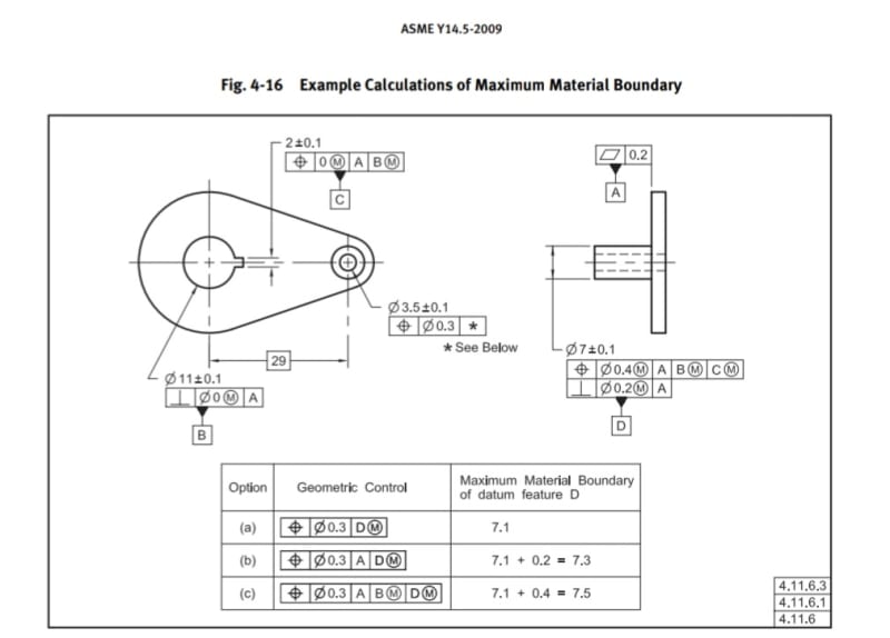
The main purpose was to explain my understanding of the reasoning behind how the MMB is calculated for case (c) of figure 4-16 in Y14.5-'09.
"For a correct analysis of the shape and size of the MMB boundary of datum feature D in option (c), one has to understand the translation and rotation constraining aspects of the relevant datum reference frames, and the step by step establishment process of these datum reference frames.
First, the position and perpendicularity controls for the 7mm pin. The perpendicularity control references datum feature A only, and creates a 7.3 virtual condition boundary for the pin's orientation, not taking into account it's location.
For the position control, a datum reference frame is established constraining 6 degrees of freedom: datum feature A constrains 2 rotations and one translation. Suppose those are u, v, and Z. The first plane of the DRF is established, coincident with datum A. Datum feature B(M) constrains two translations: X and Y and establishes the other two planes of the datum reference frame, intersecting at right angles at datum feature B axis, which is also the Z axis. And here is an important point: these two planes are the origin references for the location of the pin. By now, there is already a cylindrical virtual condition boundary that exists, and the size of this boundary is 7.5mm, as results from the tolerance of location applied and the MMC size. But, this boundary is still not constrained in rotation around the Z axis (datum axis B): it can be anywhere 360° around it, at a fixed distance of 29mm. The tertiary datum feature C(M) doesn't take a part in setting the size of that boundary. What it does is locking its rotation about Z - the w rotation, by orienting one of the planes of the datum reference frame to be at the center of the C datum feature simulator.
So far, there is a 7.3mm boundary for orientation only and a fully constrained 7.5mm boundary for orientation and location.
Next, one has to look at the datum reference frame in option (c). The primary and secondary datum features are the same as in the position control for the pin. Datum reference A is taking care of all rotations but w, and B taking care of the X and Y translations. Which once again, makes for a meaningful location tolerance zone size, even though not all DOF are constrained. Obviously, the datum feature simulator for D, which will have to be basically oriented normal to A, has to be at the worst case size that will contain the datum feature, and take into account it's permissible orientation AND location. Therefore it is not the 7.3mm orientation-only boundary that is relevant. The relationship of datum feature D with A as primary and B(M) as secondary is per the above analysis of the position control applied to it:
The feature must be contained in a 7.5mm cylindrical boundary unconstrained in rotation about Z.
Once this is realized in the form of a datum feature simulator for D with the correct shape and size, it can work as a clocking datum reference for the 3.5mm hole controlled by the FCF in option (c)."
")