First of all, questions like this can never be answered properly when the valves are cut out of context.
This is also a typical "student question" from someone trying to "learn" and a lot of answers are coming from people are "guessing" which of course creates a debate.
Any valve out of context can be analyzed differently because we all have different experiences. from symbol applications.
Another problem is that there is no exact 100% commonly used standard of symbol drawings and neither there is a 100% commonly used standard of interpreting and putting symbols into system context.
Neither one of these two valves can be considered "pilot operated" since there is no external pressure signal line involved in the symbols.
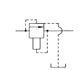
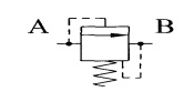
The valve to the left needs more "context" and the origin of the source. As drawn I have never seen it before. The valve to the right is as I interpret it drawn as a pressure relief valve. The control line from spring side to the B port is a drain function.
Pressure relief valves are NORMALLY CLOSED and drain to the tank.
Pressure reducing valves are NORMALLY OPEN and supply a downstream part of the system with lower and reduced pressure. As an example, the pilot lever control system in an excavator.