Continue to Site

Eng-Tips is the largest engineering community on the Internet

Intelligent Work Forums for Engineering Professionals

  • Congratulations waross on being selected by the Eng-Tips community for having the most helpful posts in the forums last week. Way to Go!

How to transfer forces from fixed beam to weld providing that fixity? 1

Status
Not open for further replies.

awa5114

Structural
Feb 1, 2016
135
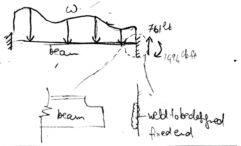
I have modeled a beam as fixed-fixed. The reaction forces are -1494 lb.ft and 761 lb (vertical). There is no horizontal reaction.

New_Doc_6_1_ymxq2x.jpg


Now I know this beam is welded to another element. I am trying to design the weld for the necessary forces. How do I transfer the reaction forces at the fixed end to the weld? Should I invert the directions of the reactions or should I preserve the same directions?
 
Replies continue below

Recommended for you

From your sketch, your beam appears to be a coped WT section. I imagine you will use a linear fillet weld on each side of the beam web, with no flange weld.

For a symmetric connection (as described above) and no axial force in the beam, the magnitude of your stresses are the same at both ends of the weld, so the sign convention won't matter.
 
And if it is a coped WT. I don't feel as though you can consider it a fully fixed connection, regardless of how much weld you throw at the web.
 
I wondered about that Jayrod, but the reactions are pretty darn small.
 
Invert the reactions to get the force and moment applied to the weld.

You should also check the coped section for the loads. Since there is "only" the stem of the tee at play at the end of the beam, it will need to resist ll the loads.
 
True enough, the stem probably works for the load and the flange is just providing bracing. I also guess all of the compression is in the web already at the fixed end.
 
I agree with Jayrod, this I wouldn't call this a fix fix. Even if the forces are small, awa should understand how he should represent this connection in a model.
 
What would the connection be if, in place of the WT, the member was a flat bar (long side vertical) fully welded at both ends? I would consider it fixed-fixed. In this instance, the full WT is stiffer than the coped ends. In order to model it, I propose a beam consisting of 3 segments. The middle segment is a WT, and both end segments are rectangular sections. End restraints are fixed.
 
It looks like this could be a carry over from your previous thread thread405647. As I said in the other thread and has been repeated here, I don't think you can call this a true fixed connection. If the loads you posted in this thread correspond to the dimensions shown in the previous thread, this isn't going to work...previous thread looks to show about 1" of welded section.
 
Agree if the other post and this post are referring to the same design.
 
The assumption of fixed ends is wrong irrespective of the amount of weld metal. The assumption of a pin at each end would be more realistic. In reality, the connection is neither fixed nor pinned. It is slightly restrained against rotation.

BA
 
I'm with jec. The connection is certainly fixed-fixed. You can model the coped section if you like, but it is such a small portion of the beam it will have a negligible effect on deflection. Two sections are critical 1.The coped section will need to resist the largest flexural stresses 2. The midspan of the beam is going to be critical for LTB. Generally this section would fail the first check since the largest moment is at the weak point of the section. You then need to size the weld such that it can develop the plastic moment in the cope, and design the beam as a pin-pin.
 
I agree that if the weld develops the full strength of the partial web that the ends of the web are fixed in the sense that they will not rotate, but the fixed end moments will be considerably less than WL/12 in the case of a uniform load. I do not believe that it will have negligible effect on deflection as the moment of inertia of the partial web is probably less than one tenth of that of the full structural tee and there will be a transfer zone adjacent to the cope in which the full tee section is only partially engaged.

From the standpoint of LTB, I think I would be concerned about the lack of lateral support for the tee flange at each end.

I would try to avoid the cope if possible.


BA
 
Status
Not open for further replies.

Part and Inventory Search

Sponsor