Follow along with the video below to see how to install our site as a web app on your home screen.
Note: This feature may not be available in some browsers.
My understanding is: A single cylindrical feature can be used to establish an axis when it is long enough to orient the part, if the cylindrical feature is not long enough(as shown on this case) to orient the part, then we need a secondary datum feature to orient/locate the part, so in this way we will have a repeatable datum axis in measurement.3DDave said:There is no use specifying datum reference B
This is where I still can't image how the runout will effect the form in this case.3DDave said:It still suffers the flaw that the much larger runout tolerance range is shown as much smaller than the size tolerance. It's sloppy work that misrepresents the situation and, by showing nearly no runout on the tapered version, when the runout is much larger than the size tolerance, is worse.
Burunduk said:
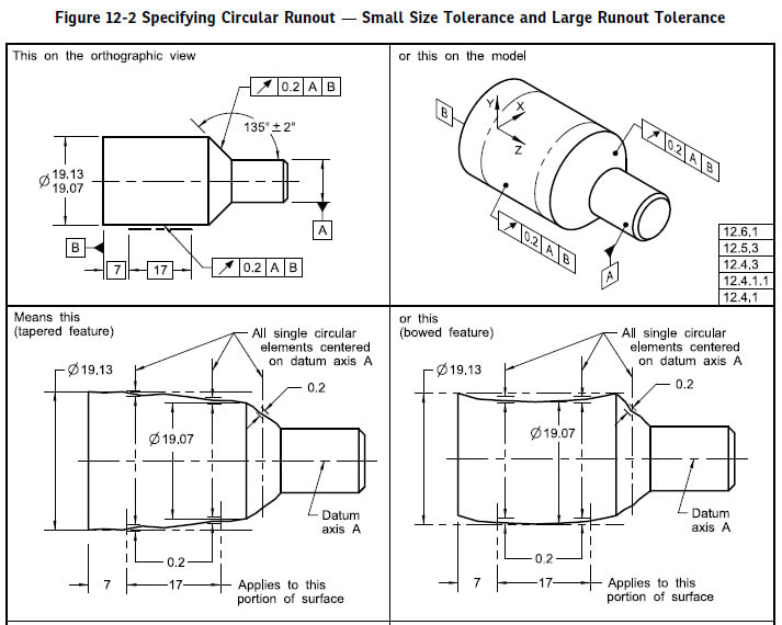
The datum axis will be derived from a simulator constructed by a component with a planar face for datum feature B to be supported against and another component with a contracting chuck the axis of which is normal to the planar face. Datum |A-B| is an axis and a plane at a right angle to it. We know that a "single datum" is not always only an axis or only a plane, because there are datum features that establish a combination of plane+axis or plane+axis+point, as indicated by the table in fig. 4-3. The combination of axis+plane I described will be established by the simulator of datum feature |A-B|.
Let me know if you still think it's invalid, and why
greenimi said:I do not think this is the way Y14.5 committee envision usage of common datum feature primary A-B.