I had started to create another model after I saw kdem's uploaded part using a graph to create the rectangular and cylindrical
portions of the cut in one shot (but in 2 halves). Later on though, I noticed that both in my new model and in kdem's model, if you
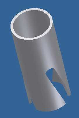
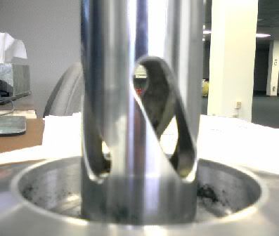
put an extruded cut of the theoretical end-mill diameter normal to the cylinder surface at a given point along the curve, you end up
with some edges. See below.
(I don't know if this would also affect James model just from looking at the pictures.)
Not it's not all that much of a difference but it still bothered me a bit, so I tried to figure out how in the world to model this.
I ended up looking at this
post. The part that Jeff
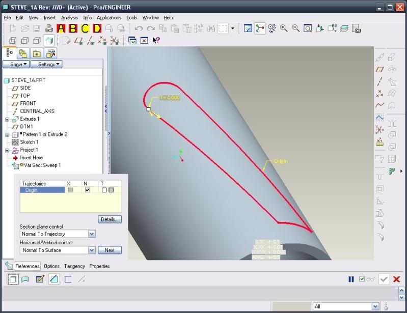
posted at the bottom of page 1 was similar to what tjallen is trying to accomplish, so I borrowed the approach of offsetting a
center VSS surface on both sides, using a VSS to generate the end surfaces and then intersecting/trimming/merging to complete the
part. This results in a model that will allow the theoretical end-mill to pass through the slot without interference.
FWIW I also tried to create the cut with a helical sweep but actually didn't create the cut correctly. It might be possible to
create the cut using a helical sweep by playing around with the cross-section but I didn't.
Attached is the final part in WF2 format. Hope it's useful (and correct this time
)
2009-04-10_150313_cylinder-vss-offset.zip