Per Evan J (from a different discussion):
One problem I always had with the description of size in Y14.5 is the emphasis on the "size also controls form" idea. The first sentence in the Limits of Size section states "Unless otherwise specified, the limits of size of a feature prescribe the extent within which variations of geometric form, as well as size, are allowed". This would naturally lead one to believe that size controls form. But the "size controls form" idea is not a rule, and does not bring in specific form controls. The form control from a size tolerance is indirect, and is a consequence of two specific geometric requirements:
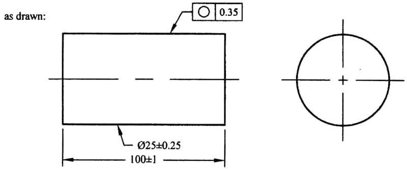
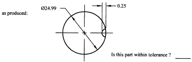
1. The feature must conform to the Rule #1 boundary (a boundary of perfect form and MMC size)
2. The feature's actual local sizes (opposed point distances) must all be within the size limits.
When these two requirements are applied to regular features of size whose points are all opposed, then the "indirect form control" concept works. If we look at the possible as-produced surfaces that meet both requirements, we see that the form error of the surface cannot be larger than the size tolerance.
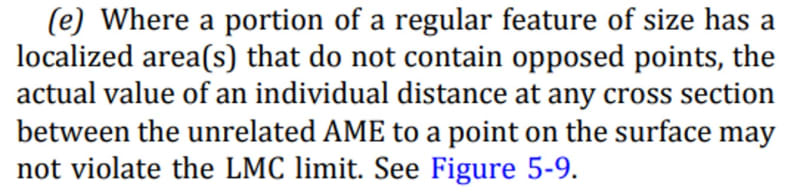
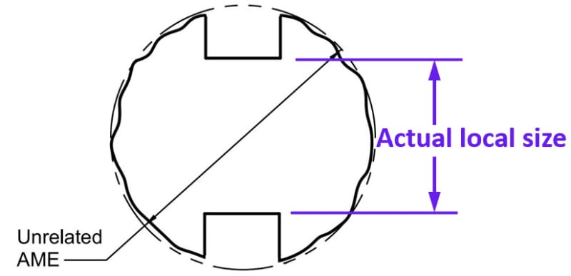
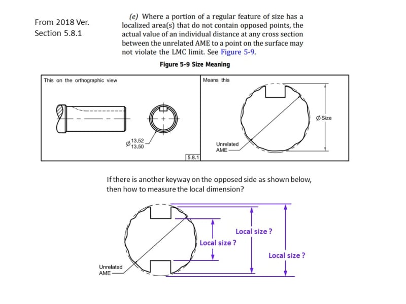
But if the requirements are applied to features whose points are not all opposed, then things change. In other words, if the feature has points that do not have a corresponding opposed point. This may be by design, as in the parts with partially opposed widths that have been discussed (or cylinders with a blind hole on one side). This may also be a symptom of the as-produced part, where a cylinder with a nominally perpendicular end face is produced with a tilted end face. In either case, we get some non-opposed points. What do we do with those?
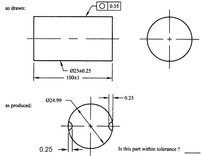
I don't think that the problem is deciding whether or not Rule #1 applies. The problem is with the definition of actual local size. In Y14.5-2009, actual local size is defined as "the measured value of any individual distance at any cross section of a feature of size". There are several problems with this definition (this discussion could fill another thread), but the main one for this thread is the idea of a "distance". This can't deal with non-opposed points. In the places where the points are not opposed, we can't define the actual local size. What is a distance when there is only one point? So the unopposed sections of the surface can pretty much do anything within the Rule #1 boundary, and we don't get the indirect control of form. To appreciate what type of control the actual local sizes apply, imagine measuring the size of the feature using a micrometer with pointed anvils. All you can measure are sets of opposed points. If the surface has areas that are not opposed, you can't measure those areas. It's as simple as that.
So what do we do with those areas that are not opposed? Strictly speaking, the form in those areas is not controlled. In most cases, this does not cause a practical concern. If the unopposed areas are relatively small as in CH's part with the blind hole, we probably assume that the surface is continuous enough that there won't be significant local deviations in the non-opposed areas. If the unopposed areas are relatively large as in CH's part with the rectangular cavity, we might not assume this. Where do we draw the line? There are no rules - this is where "practical considerations" come in. As CH alluded to, it comes down to risk management. It is up to the designer to decide whether to go with just the size tolerance or to add additional controls (if they feel that the size tolerance would allow undesirable outcomes that have a significant chance of occurring).
I'm glad that the thread is getting to some interesting outcomes. Your questions tend to make us dig deep and extract the subtle details. Keep in mind that the writers of GD&T textbooks and exercise books (and even standards) can only get into the intricacies to a certain extent, without losing most of their audience. People want things to be simple and easy, not complicated and difficult. I know from experience that it is much easier to make money glossing over these subtleties than it is addressing them. I'll stop there before I get into a self-righteous, bitter rant ;^).
I would say that Rule #1 still applies, even with features that are not perfectly opposed. Assessing the feature's conformance to a boundary is straightforward, even if the feature has unopposed areas.
Again, to me the difficulty lies in the actual local size. It's an old, shop-worn tolerancing tool that serves well for parts that one wants to be able to inspect with a caliper or mic. But for this tool to work, certain conditions have to be in place (such as opposed geometry, and form error that is relatively small). When these conditions are not satisfied, it breaks down and becomes ambiguous. It's just not as robust as zone-based geometric tolerances.
I'm not sure what will happen with the definition of actual local size - to me, this is one of the most difficult problems in GD&T. There is not even agreement on the meaning of the current definition in Y14.5 applied to cylinders, as "any individual distance at any cross section" is interpreted differently by different people. Some interpret it as a distance extracted from 2 opposed points (as one would measure with a mic), and some interpret it as a diameter extracted from a cross-sectional circular element. Unfortunately, the standard contains text supporting both interpretations and no figures that clarify the meaning (only side views are shown, obscuring what is really happening within a given cross section). So we don't even know for sure whether a cross section of a cylindrical feature has one actual local size or many. The committee is in a difficult position, because it is now impossible to choose one or the other without contradicting past practices in some way. The Y14.5.1M-1994 mathematical definitions standard created a novel definition based on an LMC sphere, but this has been largely ignored in industry (partly because it conflicts with the idea of 2-point opposed diameters, and partly because the mathematical definitions standard was itself largely ignored).
The fact that there are camps favoring different interpretations makes it likely that different types of local size are needed for different applications. The ISO GPS standards define several different types of size, but so far Y14.5 has not embraced this approach.
“Yes, in ISO GPS actual local (two-point) size of a cylindrical FOS is a distance between two points measured in a plane perpendicular to the axis of associated LSQ cylinder, and that distance must be measured across the center of associated LSQ circle.
To me this definition is mathematically consistent, although it does not address all issues. Just one example: picture a pin that is perfectly round yet is bowed to a banana shape. Per ISO definition this feature will not have all actual local sizes identical. Only in one cross section (at the middle of pin's length) they will all be equal, because only in that cross section the surface of the pin will be seen as a perfect circle. In other sections the pin's surface will be seen as an oval/ellipse-like shape, thus lead to different local size measurements. “
")