Eng-Tips is the largest forum for Engineering Professionals on the Internet.

Members share and learn making Eng-Tips Forums the best source of engineering information on the Internet!

  • Congratulations dmapguru on being selected by the Eng-Tips community for having the most helpful posts in the forums last week. Way to Go!

How to install tie rods to counter roof thrust in a barn with a central post obstruction?

marieVy

Agricultural
Joined
Aug 5, 2025
Messages
3
Hello everyone,

I'm looking for advice on the best structural approach for stabilizing the walls of an old timber frame barn.

● In short: How do you install a cost-effective anchor plate system where the tie-rod runs under a truss, bypassing its central support post without contact with the post and the timber frame?

The only solution I found is to run the rod just along the side of the post on the external side of each post. The rod would not be exactly under the truss but using a 80x50cm X shaped anchor plate aligned horizontally (cf the picture), at least one half of the X could maintain the wall under the truss rafters. But would it work if the center of the anchor plate isn't aligned under the truss rafters?

● In detail:

The Issue:
The trusses are a "raised tie beam" design, which exerts significant outward thrust on the 5 m (16ft) high masonry walls. This is causing the walls to spread and the corners to crack, with fissures on all four sides (on one side, it is running from the top all the way to the ground).

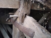
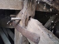
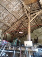
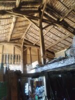
EDIT: , I forgot to mention that the mortise and tenon joint at the post's apex has failed. The truss rafters have visibly slipped downwards and away from the post. It appears to be held only by two bolted metal plates, but I don't know if this repair was made before or after the slippage occurred (see updated photo below). So it seems that the central post is not providing the assumed ridge support, and the frame might be subject to significant outward thrust, explaining why the cracking is confined to the corners. (cf? the picture)

The standard solution would be to install horizontal tie rods across the 9 m (30ft) span, located directly under each of the two trusses to counteract the thrust effectively.


Problem with the posts:

The effectiveness of a tie rod depends on its placement directly under the truss. However, the central post supporting each truss stands exactly in the direct path where the tie rod should run. This prevents a simple, straight-line installation from wall to wall.

My Question:

What is a cost-effective tie-rod system that can bypass the central post without contact, engaging solely with the masonry walls and placing no load on the fragile timber frame?

Aesthetics are not a concern, but cost-effectiveness and ease of implementation are important factors (e.g.: A double tie-rod system is not a feasible option due to cost and complexity)

Thank you for sharing your knowledge and practical experience.

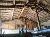
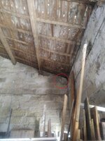
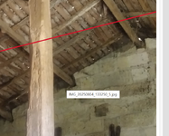
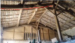
- The barn is 9m x 14m (approx. 30ft x 46ft) with two load-bearing timber post 0.2x0.2x6.5m (8''x 8'' x 21ft) IMG_20250804_133250_5.jpgIMG_20250804_133323_5.jpgIMG_20250713_192012_5.jpgIMG_20250804_133347_5.jpgIMG_20250804_133503_5.jpg
This is the type of anchor plates I was thinking about:
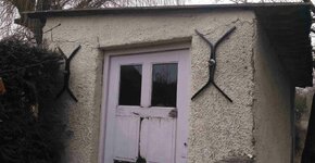
anchor.jpg
 
Last edited:
Seem more likely you have settlement or seismic happening based on your photos. There really shouldn’t be thrust since the post acts similarly to a ridge beam, though the rafter could be under sized for the load. From wall should show signs of bulging. I doubt the rafter connection could transfer that much load.
 
What's the roof pitch? I could see some outward thrust based on the low pitch the photos appear to indicate.

Assuming all the OP's assumptions are correct, I haven't looked through the post yet, but to address the question, why are you unable to place a tie rod concentrically through the post? Posts look like they might be 8" wide or so, think you could easily drill a 5/8" hole for a half inch rod and not affect the performance of the post anymore than when someone chewed half of the upper quarter off .
 
Why try to attach to the masonry to resist the thrust of the rafters? Why not just attach directly to those timber rafters? I'd look at adding anchor plates to both sides of those timbers (through bolted at the ends of the timber rafters) to attach rods or cables on each side of the post.

1754427946871.jpeg

Something similar to what you see at the ends of the steel rod in the picture above, but with one on each side of the timber rafters.
 
I am not seeing significant thrust here, not in the typical sense anyway, as long as there is a post at the ridge @ each frame. Ridge would need to drop for there to be much of an outward thrust component in the frames themselves.

This looks more like a simply-supported sloped beam (maybe overspanned) to me.
 
I just want to point out how this issue reminds me of downtown Charleston... Lots of old masonry buildings there that had issues in an earthquake back in 1886. One of the solutions was to have a metal plate on the outside of the masonry wall. This was connected to a tie rod of some sort. The Charleston issue probably wasn't exactly the same issue, of course. Probably not a truss, but more to strengthen the roof / floor anchorage to the wall to avoid pancaking of the structure.

However, I will mention it because it ended up being a pretty elegant solution for a lot of buildings in Charleston. My guess is they're still doing it for new construction. It's just so common on their buildings.
 
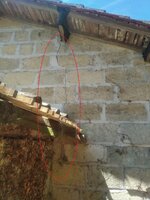
@jhnblgr: Yes, settlement could be a factor, but the cracks are confined to the four corners, with none elsewhere on the walls (see a picture below of another crack at another corner).

@ChorasDen : The roof pitch is 18° (33%). Yes, the post is 8" and the rod will be M24, but it's quite easy to mess up the hole in the post for the rod as it must be perfectly aligned both vertically and horizontally while working with the heavy rod - any tiny alignment error would result in a bigger hole.

@BridgeSmith: But with this system, the post is still in the way.

Importantly, I forgot to mention that the mortise and tenon joint at the post's apex has failed. The truss rafters have visibly slipped downwards and away from the post. It appears to be held only by two bolted metal plates, but I don't know if this repair was made before or after the slippage occurred (see updated photo below). So it seems that the central post is not providing the assumed ridge support, and the frame might be subject to significant outward thrust, explaining why the cracking is confined to the corners.
IMG_20250713_192012_5.jpg
IMG_20250804_133435_5 - Copy.jpg
 
I agree with others that you shouldn't be having thrust if you have central post.
 
I agree with others that you shouldn't be having thrust if you have central post.
Even with the new information added (the truss rafters have slipped downwards and away from the post — see the picture in my previous response above)?
 
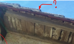
I agree about there not appearing to be thrust from sag of the peak. The rafter closest to you on the left side in picture 4 looked bowed more than others. Is it really bowed or is that just the way the picture looks?

The masonry crack the size shown in the picture for a building of this age does not look excessive to me. For any old building, it is best to take a lot of benchmark measurements including plumbness and digital photos before you start to modify it. Nice to know what is new versus old.
 
Fairly poor connection here. Could be part of the problem.

1754448475151.png
 
So it seems that the central post is not providing the assumed ridge support, and the frame might be subject to significant outward thrust
If this is accurate, I would first focus on fixing the load path to the posts. As noted by others, if the load is getting to the posts, you really shouldn’t have significant outward thrust at those locations. Unless there’s something else going on, I see no need for tie rods at the trusses.

I would expect more outward thrust halfway between the trusses where you probably have ridge beams that are sagging. Maybe the rods make more sense there.

If the original question is even still applicable, I agree with drilling a hole through the post for the rod to pass through. Or drill a hole and install a bolt which would connect to two rods, one at bolt head and one at a nut at the end of the bolt. A third option would be to allow the rod to bend around the post. I doubt the lateral force on the post would be much.
 
Haven’t seen anyone suggest two rods, one on each side of the post, to balance the eccentricity. Agree that this likely isn’t a thrust problem, but OP was there and I wasn’t.
 
You have the classic barn problem. Undersized members. The rods suggested seem unlikely to correct this problem, but different arrangements may. It seems like the time to replace or reinforce parts. Your dead loads appear to be large here. The cracks and joint problems you see are the result of long term distortion.

1754486505885.png

1754486620288.png
 
Last edited:
I just noticed the roof covering Brad pointed out. In addition to what looks like a really heavy tile roof, are you also in a heavy snow area?

Is the crack you show in picture 5 a main rafter from the primary structure frame or is that a purlin end. Looks like a purlin since I see a similar end very close to it.
 
Aesthetics are not a concern, but cost-effectiveness and ease of implementation are important factors (e.g.: A double tie-rod system is not a feasible option due to cost and complexity)
I would not rule out any workable option at this stage. In the early stages of problem solving, applying job-specific criteria tends to limit creativity. See what people come up with first, then apply criteria like cost.

You have 2 issues, first, what is causing the problem, second, how to cure it. At this stage, there is no big consensus on the cause.

This is purely speculative at this point, but if you cannot afford double rods, there may not be an option that costs less other than the standard "Do Nothing and See If It Gets Worse".
 
if the post connection has failed the tie rod does nothing, there obviously is still a connection or the roof would be collapse. Show pictures of a bow in the wall, all the info so far provided doesn’t show anything of evidence of thrust. There doesn’t appear to be any signs of slippage as you say, the collar ties would prevent that likely. The wall isn’t rigid enough likely to transmit loads to the corners without the wall at the load point showing signs of distress. Hold a level to the wall at various locations, if thrust is happening it will lean out the most there, but if it’s only at the corner it’s not from thrust.
 

Part and Inventory Search

Sponsor

Back
Top