Continue to Site

Eng-Tips is the largest engineering community on the Internet

Intelligent Work Forums for Engineering Professionals

  • Congratulations cowski on being selected by the Eng-Tips community for having the most helpful posts in the forums last week. Way to Go!

How to desgin masonry walls with in plane bending moment to AS 3700-2018

Status
Not open for further replies.

atef81

Structural
Jan 7, 2010
12
Hi All,

I was tasked to design reinforced core filled masonry walls for loads I was given.
The walls have axial compression loads and in plane bending moment.

I can't find resources that explain how to design masonry walls against in plane bending moment to Australian Standards AS3700.
Or at least what is the concept that I have to follow.

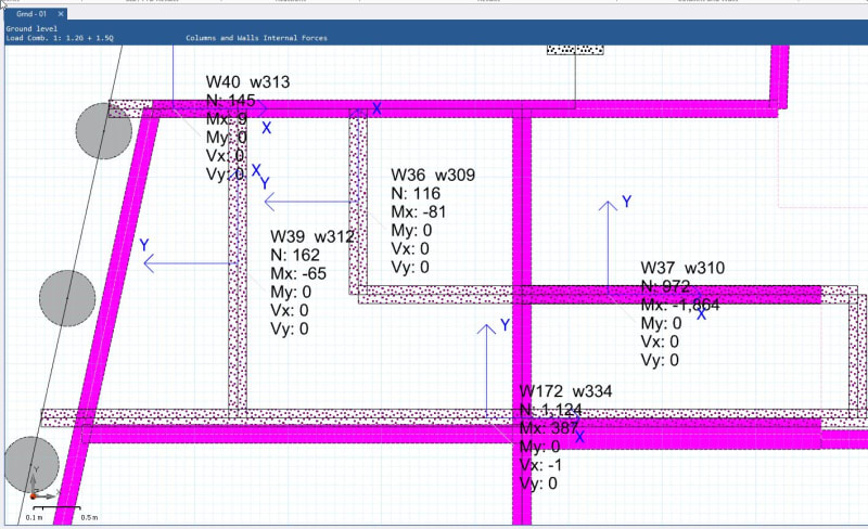
I attached an example of the internal forces on the walls for one of the load combinations.

Please note that this screenshot is from Inducta RCB software. Inducta system puts the moment in the direction of the axis, not about the axis. (So Mx is the same direction as Sx; and all are in the local x direction of the wall)

I appreciate any guidance to a method, even using first principles.
Thanks in advance

01_-_1.2G_1.5Q_w6keon.jpg
 
Replies continue below

Recommended for you

Not familiar with that software, but I fail to see how you can have moments without shears.
 
Atef81, I would recommend using CMAA design manual which can be found on their website ( but PLEASE have an experienced engineer look at your design before using them for anything that will be constructed, not doing so will be negligent. Our profession has suffered enough already.
 
You need to break your walls up in to segments of about 2-3m long (or smaller - see below) otherwise you do not pick up the variation of forces along the wall.

The way to design for inplane moments is to consider a subdivision of the walls into design segments similar to how it is done in AS3600.

Capture_pu17wl.jpg


EDIT: Typo
 
Along the lines of Retrograde's post.

If these aren't designated as shear walls and are gravity walls, computer programs are terrible at giving you axial loads/unit of distance which is how you would determine the loading using tributary area. Because the analysis for the wall yields stresses on the finite element mesh these can more easily be turned into a P and M about the wall panel center, using the standard P/A +/- M/S you can then back into the axial load variation at the top of the wall the end result of which will be similar to the procedure in Reotrogrades post.

Hokie66 said:
Not familiar with that software, but I fail to see how you can have moments without shears.
Assuming gravity walls, the Shear is all internal to the wall panel. The true loading on the wall panel looks more like the image in Retrograde's post but the program interprets it as to total area under the curve as P at some eccentricty from the wall panel center point,e and reports the wall load as P and M=P*e.


My Personal Open Source Structural Applications:

Open Source Structural GitHub Group:
 
Status
Not open for further replies.

Part and Inventory Search

Sponsor