I am not sure I understand everything from your last post, so forgive me if this reply does not address all your questions well.
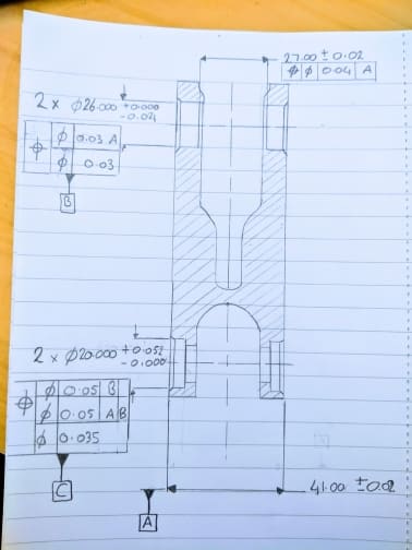
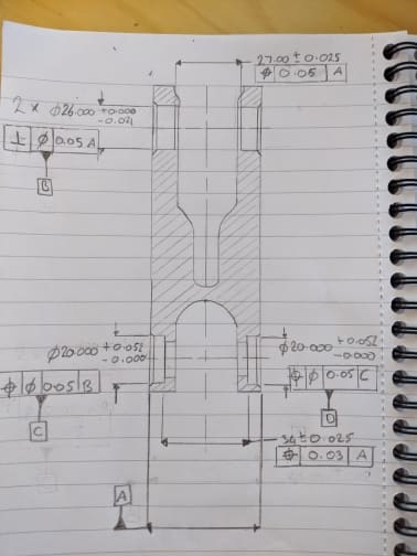
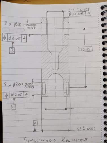
-- The relationship between 4 cylinders can be addressed by applying position tolerances relative to datum A only. There is a concept in Y14.5, called 'simultaneous requirement', that says that unless otherwise specified, the features controlled with position or profile tolerances that reference the same datums, in the same order, and at the same material boundary shall be considered a pattern. In your case the position tolerances relative to A only would create a group of 4 cylindrical tolerances zone (2 pairs of 2 coaxial cylinders) perfectly perpendicular to the datum center plane A and spaced at basic distance apart (which by the way is missing on your drawing).
-- Regarding the difference between different versions of Y14.5. Some will say the differences are minor, some will say otherwise. That depends on who you ask. In the parallel thread started by you about straightness tolerance,
I gave an example of a difference between '94 version and higher versions. And there are more. For instance, '94 version did not show any examples of composite tolerances with more than 2 segments and many people literally took this as no-no for three-segment composite callouts. As you already noticed in another thread,
newer versions of the standard clearly allow for this kind of callouts.
-- Yes, in addition to being a perpendicularity control relative to A, the position applied to 2 datum features B will also control axes offset. Perpendicularity tolerance alone is not capable of controlling the latter.