Continue to Site

Eng-Tips is the largest engineering community on the Internet

Intelligent Work Forums for Engineering Professionals

  • Congratulations KootK on being selected by the Eng-Tips community for having the most helpful posts in the forums last week. Way to Go!

How to change the MCS of the "Geometry" view

Status
Not open for further replies.

wedxza

Mechanical
Jun 25, 2015
20
Hi, everyone,

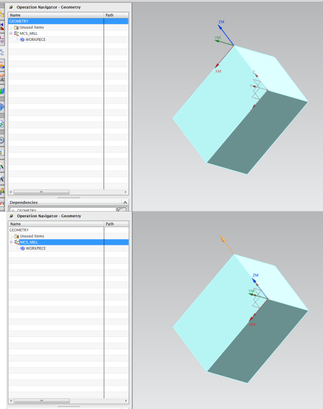
Felt a bit confused about how to set the coordinates for "Geometry" view.

In the "Geometry" view, the origin of the MCS is on the top of the part.
In the "MCS_Mill", origin in on the bottom of the part.

I wonder if I can change the MCS to the bottom for the "Geometry" view.
Details are shown in the pics.

Thanks for helping
2_is1yw3.png
3_mpxlmy.png
 
Replies continue below

Recommended for you

why do want to change it?

Anthony Galante
Senior Support Engineer


NX3 to NX10 with almost every MR (21versions)
 
If u know the answer pls let me know.
 
it can't be changed and I can't understand why you feel the need to change it.

Anthony Galante
Senior Support Engineer


NX3 to NX10 with almost every MR (21versions)
 
Why it was labeled as XM, YM, ZM? Is that another machine coordinate system(MCS)?
If it is the absolute coordinate system, should it be labeled as X,Y,Z?

Wonder if that coordinate system (MCS of the "Geometry" view) will have effect on the manufacturing processes.

Thanks
 
The MCS is the Machine Coordinate System. This is the origin of the NC program.
It can be moved wherever you want it just like the WCS (Work Coordinate System). You CANNOT move the Absolute coordinates.

I appears to me that you need to have some training on the use of NX.. Have you reviewed the help docs?


John Joyce
N.C. Programming Supervisor
Barnes Aerospace, Windsor CT
NX7.5, NX9.0, NX10.0(Testing)
Vericut7.3.3
 
Uh... Denying me won't help.

Do you mean that the "MCS" in the "Geometry" view is actually the "absolute coordinate system"?
But why it is labeled as "XM, YM, ZM", is the absolute one labeled as "X,Y,Z"?

I felt no one really directly answered my questions

Thanks for your patience, and your understanding
 
If you select the root (top) node in the geometry view, you will see the absolute coordinate system, since there is no MCS defined at that level. This is expected, and not a problem, because operations should always be under an MCS group, which determines their output coordinates.

For a little experiment, create several MCS groups at different locations or orientations. Now create a simple milling operation and generate the path. Now drag it under each group, and the root node, and list it at each location. You will see different coordinates, even though the path has not been regenerated.


Mark Rief
NX CAM Customer Success
Siemens PLM Software
 
I tried in the manufacturing simulation, and the machine will always take the MCS of the "Geometry" as its origin.
I need to manually set an offset for it in order to avoid the errors.

If I set the MCS of the workpiece on the bottom, and the MCS of the "Geometry" is on the top, there is an error. (I need to set an offset to correct it.)
If both MCS of the worpiece and "Geometry" are on the top, there is no error, and consequence is as expected.

Thanks a lot. I will try in your way.

Wonder if it is the problem of the simulation software that I am using.
 
Uh...Now it seems a bit clear that the "XM,YM,ZM" of the "Geometry" is not the absolute one
Probably is, but why it is labeled the same as "MCS". The "X,Y,Z" is called the "datum coordinate system", and I can move it... so it is not the absolute coordinate system......
Just wonder if there is any way to change it

I tried to find in the help file, only found how to set it up. nothing specific related to the Geometry view "XM,YM,ZM"...

Thanks
absolute_izowbr.png


I'm confused trying to understand this, so let's try some CSYS review so can communicate with the same terminology.

There is one absolute CSYS. It cannot be moved. It is not displayed. It can be used as a reference (e.g. you can define a datum CSYS at absolute).

Datum CSYS and CSYS are entities that can be saved and referenced.

XC YC ZC is the WCS = Work Coordinate System, used for user input in NX. There is only one WCS at any time. Move it anywhere, or select a saved CSYS. It is not used for any CAM output.

XM YM ZM is the MCS = Machinine Coordinate System, used for CAM output. You can define as many as you want. The one used for ouput is based on where the operation is in the Geometry View of the Operation Navigator.

MCS can have options for its useage. For example you may have one main MCS for the origin, and several others for fixture offsets.

Mark Rief
NX CAM Customer Success
Siemens PLM Software
 
Problem solved. The key is to define the origin of abs coordinate on the top of the workpiece in simulation(same as the WCS of the "Geometry" view).
No matter how I set MCS, WCS, reference, it didn't matter. Although the outputs are different...

Weird results and thanks for helping
 
@wedxza
I understand exactly what you're talking about and I agree the behavior is a bit unexpected. At least in Program view. It goes back to absolute but that's really not where your mcs is set. If you select an existing operation you will see that it is set where you created the mcs and if you create new operations with that mcs they will display properly.

I understand what Mark is saying but I still feel that behavior is somewhat unexpected since the mcs is "specified" but it can display differently. That seems inconsistent to me but oh well.

NX9
Migrating to 10 when 10.2 is released.
 
Status
Not open for further replies.

Part and Inventory Search

Sponsor