Hi Members,
I am trying to calculate the hot water recirculation flow for several balancing valves. I am following the procedures outlined in the ASPE Plumbing Engineering Design Handbook Volume 2, Chapter 6. However, once you have more than one recirculation path the process becomes a little bit confusing.
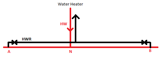
For Example: in the system shown, I can calculate a heat loss from the water heater to node C, a heat loss from node C to node A, and a heat loss from node C to node B. I can then calculate the heat flow corresponding to each of these heat losses, and I can assign the flows to each of the balancing valves. However, since the heat loss from the water heater to node C is shared by both recriculation paths, It seems logical to me to assign only a fraction of this flow to each of the balancing valves, i.e.:
Balancing Valve A: Flow corresponding to heat loss node C-node A + fraction of flow corresponding to heat loss water heater-node C?
Balancing Valve B: Flow corresponding to heat loss node C-node B + fraction of flow corresponding to heat loss water heater-node C?
My question is: How do you calculate the fraction of the flow corresponding to the heat loss from the water heater to node C that will be assigned to each balancing valve? The ASPE Plumbing Enginneer Design Handbook Volume 2, provides Equations 6.9a and 6.9b. However, I am yet to understand how to use them.
The question becomes more interesting once you have several divisions of flow and several hot water return paths and balancing valves.
Thanks!
I am trying to calculate the hot water recirculation flow for several balancing valves. I am following the procedures outlined in the ASPE Plumbing Engineering Design Handbook Volume 2, Chapter 6. However, once you have more than one recirculation path the process becomes a little bit confusing.
For Example: in the system shown, I can calculate a heat loss from the water heater to node C, a heat loss from node C to node A, and a heat loss from node C to node B. I can then calculate the heat flow corresponding to each of these heat losses, and I can assign the flows to each of the balancing valves. However, since the heat loss from the water heater to node C is shared by both recriculation paths, It seems logical to me to assign only a fraction of this flow to each of the balancing valves, i.e.:
Balancing Valve A: Flow corresponding to heat loss node C-node A + fraction of flow corresponding to heat loss water heater-node C?
Balancing Valve B: Flow corresponding to heat loss node C-node B + fraction of flow corresponding to heat loss water heater-node C?
My question is: How do you calculate the fraction of the flow corresponding to the heat loss from the water heater to node C that will be assigned to each balancing valve? The ASPE Plumbing Enginneer Design Handbook Volume 2, provides Equations 6.9a and 6.9b. However, I am yet to understand how to use them.
The question becomes more interesting once you have several divisions of flow and several hot water return paths and balancing valves.
Thanks!