Hi Rwelch9,
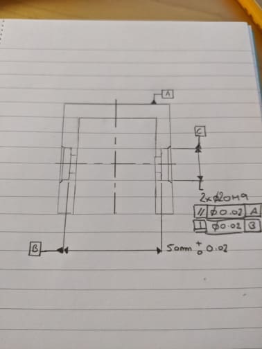
I would start with a flatness tolerance on datum feature A. Then a perpendicularity tolerance relative to "A" applied to each of the two planar surfaces from which the datum B center plane are found. That perpendicularity could instead be applied to the center plane by placing it under the width dimension between the two planar surfaces, but there's no significant benefit and I think that adds difficulty.
Instead of the parallelism to A and perpendicularity to B that you show applied to the two cylindrical pockets in your sketch, I think:
|position|dia x.xx|A|B|
should work fine. To establish that datum reference frame (DRF) you need to find a center plane from the two planar datum feature B surfaces then project that as a line down onto datum A. If you then probe the two cylindrical pockets you should be able to get a result for that position tolerance. If would be much better if those planar datum feature B surfaces had a larger footprint. I'd be concerned that repeatability in rotation about the Z axis that those small planar surfaces can provide may not be good enough. If the repeatability isn't good enough then using the measurement results to tune the machining might turn out to be a "tail chasing" exercise. To avoid this it would be a good idea to set up the datum reference frame separately and independently 5 times, then check the repeatability of your results for the position tolerance on the cylindrical pockets. If the variation in your position values is greater than 20% then I wouldn't trust the data.
Also, is your CMM machine driven, or are you probing points manually? A machine driven CMM, and also iterating, to establish the DRF 3 times is necessary to ensure that you probe the same points accurately enough each time. This may sound odd, but think about the points you probe being located relative to the coordinate system that you're constraining with those same points. For the first iteration, you eyeball the probing locations, then establish the DRF from those points. The second time, you have the CMM drive to coordinates on the features that are relative to that first DRF, then establish the DRF from that second set of points. Repeat that one more time, with the 3rd iteration points located from the 2nd DRF you established and then that 3rd go at the DRF should be repeatable enough. If you come back and measure the part again, with that looping in the program as you establish the DRF, you should get a repeatable result. If you complete that iteration process and the DRF is still not repeatable, based upon variation in data measured relative to it, then the datum features may not be capable enough or some other source of uncertainty is causing the issue.
If your CMM is not machine driven, then getting adequate repeatability to enable reliable enough data to use for tuning the machining process is probably a long shot.
I think the functional requirement for coaxiality may not be super tight. They're so shallow that the mating pin/shaft may do fine with your first pass at machining the pockets..?
Dean