Continue to Site

Eng-Tips is the largest engineering community on the Internet

Intelligent Work Forums for Engineering Professionals

  • Congratulations The Obturator on being selected by the Eng-Tips community for having the most helpful posts in the forums last week. Way to Go!

Hand calc procedure for eccentric loading

Status
Not open for further replies.

kingnero

Mechanical
Aug 15, 2009
1,780
As some of you know, I'm mostly active in railway welding applications.

I was asked to look at a temporary repair of a broken rail, with a specific methodology.
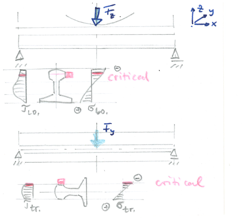
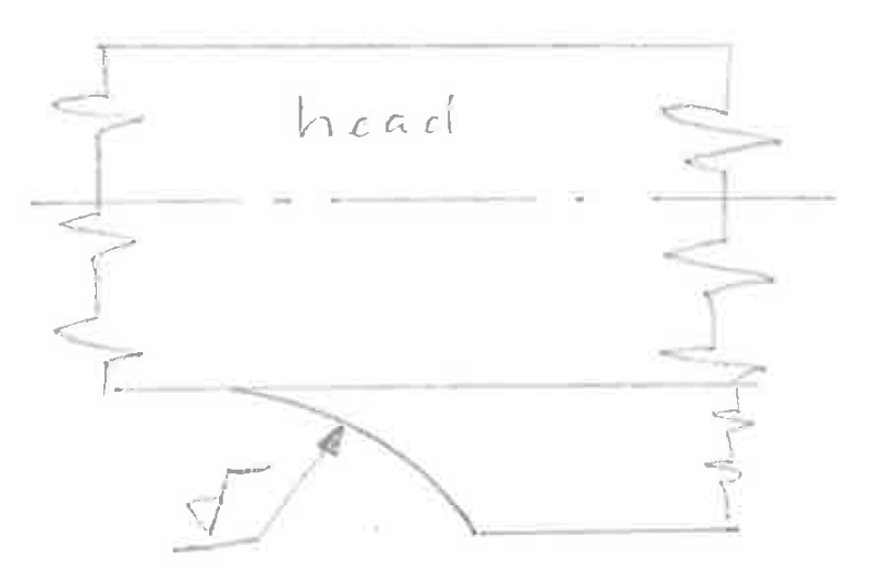
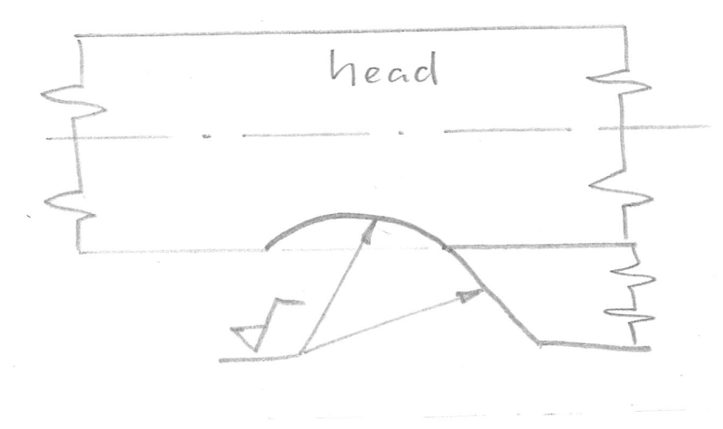
This consists of welding a piece of hi-strength steel to the outside of the head of the rail. (see attachment)
This is chosen because in urgent situations, a complete repair isn't feasable.
This temp solution should only work for a limited period (think hours, maybe days, but certainly not weeks). So fatigue isn't to be considered, as the repair will also be monitored from closeby.

I've got the welding procedure itself quite covered, but I still need to evaluate the strength of the repair.
Note: I've left the weld indication blank on the sketch, as I'm used to ISO designations, and not too sure on AWS specs. It's simply filling a half V groove (between rail head and steel bar) with weld metal.

The forces are vertical (gravity load, dynamic) and sideways towards the outside (due to the dynamic movement of the train), with a ratio of 2:1 (vertical to horizontal).

There will be primarily shear on the cross section of the steel attachment (+ weldment).
I believe bending will only be minor factor, but I don't know how to quantify this.

Any suggestions on how to tackle this?

I am a big enthousiast of simplifications and overdimensioning, but here the physical space available doesn't leave much room for overdimensioning. The shear capacity of this attachment is 120% of the necessary, in my simplified "napkin"-calc.
and this didn't take into account the eccentricity and the bending.

So, I'm open to all suggestions...
 
 http://files.engineering.com/getfile.aspx?folder=6600e28e-bf6a-46cf-9c10-3a42b2a7ca2c&file=scan_suggested_solution.pdf
Replies continue below

Recommended for you

I think The size and location of the single high strength bar would subject it to immense alternating bending and twistin to handle all by itself as the wheels roll past. I think that is true regardless whether the break is over a tie or not. I'm guessing the break likely occurs at a location of highest stress , or maybe just at welded joints.

 
I know there will be "immense" stresses involved, but don't know how to quantify these.

I am well aware of the common repair procedures (fishplates, thermite welding, joint welding in cupper shoes, ...) but for this particular case, a traditional repair method isn't feasable, as the rail, in this specific location, is continuously supported on concrete, and encased as well. This greatly affects the repair possibilities, and makes it necessary to renew the rail over a greater length, to the points where rail joining is possible.

The fact that it is continuously supported, also affects the vertical forces to a certain extent (there is a rubber padding under the rail for its damping properties).

i'm more looking for an analytic way to support my gut that this repair method suffices for the loading that it will see, and for the time that it will see it.
 
For an analytic procedure, consider the rail supported on a continuous flexible foundation, the neoprene pad, and use Roark or similar to analyze the rail.
 
Hi kingnero,

What is your weld symbol signifying ?

==============
"and encased as well."

Time for a picture of the "big picture."

regards,

Dan T
 
Symbol means field weld.
Big picture will come on monday, unless I find some pics on my home computer.

Buggar, doing so won't take the eccentricity of the loading into account...
 
Why not use bolted rail joints which are already proven in their use instead of welding plates?


why
 
Why not thermite, as has often been used? That's pretty fast. At the least the same leveling and alignment needs to be done.

for example.

I would not want to play croquet with those guys.

Alternate, use an oxygen lance to punch holes and bolt a conventional splice plate on as suggested above. Or use a drill. I like the sparks from the lance, but that's just me.

I think the biggest problem is vertical shear. As each wheel passes from one segment to the next the reaction will be removed from one and put to the next and the only thing resisting the weight of the wheel is going to be your welded splice. I think this is why bolted splice plates or full thermite welds are used. If the ties and ballast were perfectly rigid this deflection transfer would not be a problem, but that's not the case.
 
Here's already a quick google view picture, to refrain others from suggesting traditional repair methods as well.
As I said before, fish plates, thermite welding and joint welding in cupper shoes simply aren't possible, rail needs to be renewed as a whole in the concrete blocks. Which can't be done instantly.

HermOW.jpg


On monday, I'll be able to show more detailed pics and cross sections.
But either way, I'd like to focus on the calc side, not on the repair method side.
 
I figured I recognized the field weld part, but wanted to confirm the weld is on the "other" side of where the arrow points, in the V bevel that ??may?? be a weld prep.
Is the intent to run a bunch of weld passes to "fill" the V bevel?

So, the result would be the new rectangular bar doing all the work, possibly with a pre-existing crack (the broken rail)?
Or, the new rectangular bar will attach at some distance from the rail break, skipping a section several inches long right at the rail break?
 
In reading your original question you forgot to mention that access to the rail was severely limited because -IT IS CAST INTO A CONCRETE SLOT-

You are asking in the Mechanical engineering other topics and not the Structural or Welding forums, so too bad, you get alternates. Sorry for the distress.

Since it doesn't matter if it fails, then skip the calcs and just do it. Or just skip the repair at all and closely monitor.

Eccentric welding will try to pull the rail out of straight, the amount depending on the pre-heating** and post-weld cooling,
leaving large strains in the weld area right next to a crack; another reason to skip it and just replace the rail.

What is interesting to me is that there should be a plan filed for the method to replace concrete trapped rail at that crossing, but whoever
is now in charge doesn't have it or doesn't know to look for it. Perhaps the original designers just skipped that part of rail maintenance
planning or figured that any problem should be solved by tearing out the entire crossing and building from scratch, which is how highway
departments usually seem to work.

Perhaps make up a test section of the same rail material/section to replace a more accessible section of track to check the weld method and
run test stock over. Sorry, overstepping my bounds again.

** There may be no way to adequately pre-heat the rail in close proximity to concrete. Even a little MAPP gas torch will cause concrete to explosively
spall, and much more heat is needed to heat the rail enough that there aren't quench cracks in the weld.
 
Since it will be a temporary repair, chip off enough concrete to install rail joints compatible to the rail size instead of welding plates which will probably break sooner than the temporary period
and recast concrete around the rail joints.
 
3DDave said:
I think the biggest problem is vertical shear. As each wheel passes from one segment to the next the reaction will be removed from one and put to the next and the only thing resisting the weight of the wheel is going to be your welded splice. I think this is why bolted splice plates or full thermite welds are used. If the ties and ballast were perfectly rigid this deflection transfer would not be a problem, but that's not the case.
Yes! That’s where I want this discussion to go. See below, I’ve got deflections and forces, but not the knowledge to do anything with this.

Tmoose said:
Is the intent to run a bunch of weld passes to "fill" the V bevel?
Yes indeed, that’s the idea.

Tmoose said:
So, the result would be the new rectangular bar doing all the work, possibly with a pre-existing crack (the broken rail)?
This. The bar will span the gap (the gap will have a max size of 20mm or about ¾”), and will prevent differential movement.

3DDave said:
In reading your original question you forgot to mention that access to the rail was severely limited because -IT IS CAST INTO A CONCRETE SLOT-
Nope, I said space was severely limited. The rail is cast in a sort of resin, in a steel casing, in a large concrete block.

3DDave said:
… so too bad, you get alternates. Sorry for the distress.
No distress, but nobody seems to be wanting to tackle the real problem.

3DDave said:
What is interesting to me is that there should be a plan filed for the method to replace concrete trapped rail at that crossing, but whoever is now in charge doesn't have it or doesn't know to look for it. Perhaps the original designers just skipped that part of rail maintenance planning or figured that any problem should be solved by tearing out the entire crossing and building from scratch, which is how highway departments usually seem to work.
Not correct. As I said, this is a temp repair. All long-term replacement protocols are in place, and are applied at the right time. This is a repair that will be executed in order to let the trains that are currently on track pass with a slightly higher speed than prescribed in the reglementation. A rail break at this specific location causes a huge bottleneck during peak hours, because they have to pass this section at 20 km/h (nominal speed of this section is 120 km/h). Even at 40 km/h, delays will be significantly less. Once the trains on this section have passed, cranes and workers will replace the rails, and further trains will be deviated onto another track. But you just can’t make trains drive backwards for the last-passed switch. So they have to pass, and preferably at a speed higher than 20 km/h.

3DDave said:
Perhaps make up a test section of the same rail material/section to replace a more accessible section of track to check the weld method and run test stock over. Sorry, overstepping my bounds again.
I’m having a test section mocked up, and have performed several tests, which gave me the displacement in function of the forces applied. This because the resin has mechanical properties that are known (spring constant, …), but there are also tubes for draining water, which makes empirical testing necessary.

Xsection%20HOW.jpg


3DDave said:
There may be no way to adequately pre-heat the rail in close proximity to concrete. Even a little MAPP gas torch will cause concrete to explosively spall, and much more heat is needed to heat the rail enough that there aren't quench cracks in the weld.
I’ve had several hardness tests done on a number of welded pieces, with a special choice of filler material and different preheat temperatures. When you choose an austenitic filler, you can significantly drop the preheat without risking HIC or other cracks. Spalling of the concrete is no risk, burning the resin was one of the major issues. But we can drop the preheat so much that even that isn’t an issue.

Chicopee said:
Since it will be a temporary repair, chip off enough concrete to install rail joints compatible to the rail size instead of welding plates which will probably break sooner than the temporary period
and recast concrete around the rail joints.
Won’t be doing that for a repair that only needs to last a very limited time period…

Chicopee said:
Here is an attachment which could be of help. ( “introduction to track design” )
Thanks for the idea, but I think with my 10+years of experience in this area I have chosen a repair method that is both feasible and sufficient. I just need some ideas to get started to quantify this, even an approximation, as this is out of-plane shear ( K III c failure mechanism) with a pre-existing fissure, and with an eccentric loading.
 
pls. forgive me if something doubles up previous posts, it is just to have the overall picture

mech. theory:
As the geometry is complex and the forces applied multiplanar, this would be roughguessing at least for hand calculations, if those are feasible at all.
For a discreet (point) supported rail, from basic appl. mech.s, the picture would be that you need to overlay at least two planes:
2377_001_tfs2r1.png

However, as you are moving on continuous support and with a crack in the profile, & given the level of complexity I'd propose to have the job of load analysis done by some reputable engineering team by FEA.

practical:
A test rig & rigorous testing is imo, due to the safety relevance of your application, an absolute must. Other way round: No test No go.
For the very important end areas of the repair patch, I'd propose an end mill after welding:
2378_001_y0bhwt.png

However, as you cannot run a heat treatment after welding and the intrinsic stresses from welding that much material together will be significant, you need to consider that if one side of the repair breaks off the patch might spring upwards like a finger.

legal:
If you are british, I'm sure as hell the RSSB will want to have a look on this. If neerlandais, well there's surely a local analogy of that board. I would not recommend to run this procedure offside the authorities with the (for want of a better word) excuse of a temporary repair.
This is transport, there's people onboard and around.
I hope this does not collide with the 10+ ys experience ;-), so pls. accept a "best of luck"

Regards


RSVP
 
@ RolMec,
thanks for your effort.

Here are some reflections:
- I agree with your sketch. I suppose the indexes lo and tr mean longitudinal and transversal. These are indeed the forces and stresses that are to be considered.
- I'm not a big fan of FEA unless you can back it up with some (even rather rough) calculations. That's why I asked this question here...
- No testing, but close monitoring will be done, with the safety of the passengers in mind. IF this happens again, someone (meaning: at least a few guys) will stand nearby to watch the repair, for the few trains that will pass by until they have a window to change the rail for a new one.
- end milling in situ isn't easily possible, especially in emergency situations, but I can easily prepare the attached bar so it has a bevel, and both sides that end at an angle of 30-45° so the bottom layer will be the longest, and the layers shorten as they rise in the bevel. Same principle, but not as smooth a transition as if it were machined.
- If the repair breaks, the possibility exists that the assembly might spring up upwards. Will need to figure something out for that.

As for the legal side, this has been ordered by "the powers that be", and I've got three more alternatives which each will be presented together with their advantages and disadvantages. As I said before, they're willing to do almost anything in order to diminish the unevitable delays should this ever happen again at this specific location...
 
Hi kignero,
pls. have a look at the following:

to 1st -: Y. However, more complexity is added as at least in part the stress flow as per the sketch will have to redirect to the repair patch bar, and at that be transmitted through the welding. With the locomotive wheel going on. Perhaps you can at least approach some skilled railway building engineer with a structural calc. background?
to 2nd -: they will do this also, and you'll have done what is necessary: You sought professional support when your own base was not sufficient. Pls. consider, even with the high energy knowhow supply from eng-tips or elsewhere, you imo cannot rely on input from the net for such an application!
to 3rd -: to get some pieces of rail, weld them together in different ways and then have them tortured is imo a small treat for this big task, the more that as it seems you people seek a method rather than the "one time stand"
to 4th -: I had in mind a finger grinder like:
finger_grinder_tjzqpv.png

Same as above, I'd nevertheless suggest milling / grinding after welding, it's what I do to tune down "aggressive" corners prone to develop a crack. I'd perhaps even extend the grinding to something like that:
2381_001_ssiaxf.png

(--> Sorry for the pictures to be that big ;-)
to 5th -: test it, you'll see it. And again, you'd have done everything that could have been done.

Pls. consider: "Powers that be" may evaporate sometimes. Propose all, that is the least to be done. Again, the basic principle here would be that
"The technically competent party has to inform the less qualified / competent party, and especially so about inherent risks, if the less competent partner might undertake a misuse."
There's surely a much more concise formulation of this, maybe someone can skip it in?

Regards

RSVP
 
@ RolMec,
as for the continent question, yes, is it the picture where the cars drive on the right (pun intended) side of the road that gave it away?
"you can at least approach some skilled railway building engineer with a structural calc. background?" Uhmm, well, that's my profile, as a welding engineer that is specialized in railway applications. before this I worked design, and changed towards railway welding few years later. Just need some ideas on how others would tackle this calc. My rough calcs show that this repair is capable of 120% of the necessary strength. Which is a fairly low FoS, but due to space restraints that's all I can do. Perhaps a more elaborate calc could yield more precise results...

Good tip for the finger grinder. We've got those, will certainly use that idea.

As for the method vs. one time stand: We are looking for a written procedure for something that might never happen again. So it's more a method for a one time stand. Especially as the next time this happens, might well be in quite some time, we need a well-defined procedure (that also includes notification to certain persons), to guarantee a correct execution and follow-up.

And I do realise that "they" might evaporate, don't worry I've got that covered as well, this isn't my first rodeo.
 
I picture the highest stresses occurring in the splice bar at the rail break. Regardless, Whether the welding proceeds across the break (one weld per splice bar) , or ends just shy of the break (2 welds per splice bar.)

I don't see the a way to grind a profile that area.
 
Status
Not open for further replies.

Part and Inventory Search

Sponsor