Continue to Site

Eng-Tips is the largest engineering community on the Internet

Intelligent Work Forums for Engineering Professionals

  • Congratulations cowski on being selected by the Eng-Tips community for having the most helpful posts in the forums last week. Way to Go!

Grid system and trying to understand why the remote area would be adjacent to the near main

Status
Not open for further replies.

SprinklerDesigner2

Mechanical
Nov 30, 2006
1,264
I've never run into something like this before.

We know the decision to use velocity pressures in the calculations is up to the designer and if I am running close I will check to see if there is an advantage and while there is a difference I've never run into something this weird.

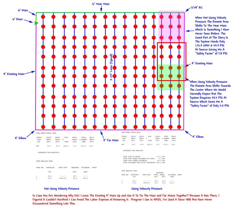
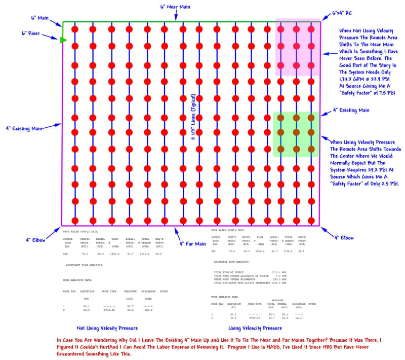
I know the grid isn't the usual with both ends of the near and far mains being connected

Grid_Question_for_Eng_Tips_nxtau3.jpg


Can anyone give me an insight as to why the remove area moves adjacent to the near main when not using velocity pressures? I am at a loss, I have never seen something like this and if a plan reviewer asks I would be at a loss for an answer.

Just noticed it is an ESFR system (K16.8 52 psi) and my calcs are heads per line for a total of 12 heads and not the three heads per line my sketch indicates. The calculations are correct at four heads per line.
 
Replies continue below

Recommended for you

I cannot understand how the application area is been shifted that much between the two cases. There should be no change when considering VPs especially when we are talking for 2 1/2" branch lines. The VPs are practically negligible. But just by looking at it, without doing calculations, not even talking about VPs, the pink area being supplied by a 6" near main, that near to the main cannot be the remote area in any way. Are you sure you are giving the correct input to the software?

I run the calculations for such system with ESFR 16.8, 52 psi, all Sch 10 pipes, 6" near main, 4 " far, all brach lines 2 1/2", pendents on welded outlets or mechanical tees, all distances btw heads equal 10' and the remote area came for me as per my red markup below for both cases (with and without VPs).

2019-04-26_12_33_23_wdhzzt.jpg
 
I started over from scratch and here I am ending up with the same exact answer.

It's really straight forward like any grid with the exception of connecting both ends of the near and far mains. I know the input is correct.

Never ran into this before.
 
Are you relying on an area auto-peeking function by the software? If yes, could it be that it fails to get it right? Have you tried to select the area I showed above manually and calculate it? Does it really show a lesser demand than the pink area adjacent to the 6" main?
 
Yes, I was relying on an auto-peak function and it failed on me.

Turn off the auto-peak and the answer is as you would expect:

Required at the source (I do have a fire pump).

1,711.9 gpm @ 21.2 psi with remote peaking and velocity pressure off. The remote area is directly adjacent to the near main.

1,712.9 gpm @ 27.2 with remote peaking and velocity pressure on. The remote area is located a little more than halfway down the grid as we would normally expect.

I turned off remote peaking and used the area given when remote peaking was on and ended up with a 1,708,1 @ 25.8 psi with remote peaking and velocity pressure off.

At 1,710 gpm I have 32.0 psi available at the source so so I am good but I sure would like the 21.2 a lot better.

I have checked this thing again and again and the input is good. For the life of me I don't understand why it is doing what it is doing. I hate to say it but I think HASS might have a bug in the auto peak.


I believe it would be a good idea to send the model to HASS people and ask them to investigate and give an answer on why it's doing this.
 
Status
Not open for further replies.

Part and Inventory Search

Sponsor