Howdy,
Would you all have a look at the image I uploaded. I'm curious how others would interpret this callout.
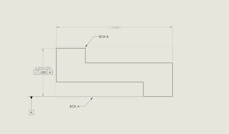
Datum A is the step on the bottom right. The surface to be parallel is the top left.
If it were to have a MMC call out, my understanding is I could make a theoretical "box a", 5.100 in width and as long as the part fit in it it's okay. Without the MMC, the box would be whatever the face measured at +.050...so a little difficult to make a test fixture... but that's what it means right?
However, I'm being told that the parallelism only applies to the top left step... and essentially I can have a .050 wide "box b" as drawn. Pretty much place -A- on a surface plate and a test indicator cant move out more than .050"
I would love what I'm being told is right. I know that was the intent of what was drawn. But, I don't believe that is what the callout on the print "says".
I ask this because I have parts that would not fit in the "box a" interpretation, but pretty much every part fits in the "box b" interpretation.
Thanks!