Continue to Site

Eng-Tips is the largest engineering community on the Internet

Intelligent Work Forums for Engineering Professionals

  • Congratulations KootK on being selected by the Eng-Tips community for having the most helpful posts in the forums last week. Way to Go!

GD&T Parallelism on a stepped part. 1

Status
Not open for further replies.

RoarkS

Mechanical
Jul 10, 2009
264
gdt2_uhoec4.jpg


Howdy,

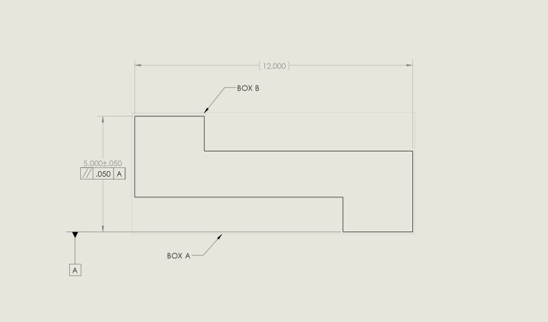
Would you all have a look at the image I uploaded. I'm curious how others would interpret this callout.
Datum A is the step on the bottom right. The surface to be parallel is the top left.

If it were to have a MMC call out, my understanding is I could make a theoretical "box a", 5.100 in width and as long as the part fit in it it's okay. Without the MMC, the box would be whatever the face measured at +.050...so a little difficult to make a test fixture... but that's what it means right?

However, I'm being told that the parallelism only applies to the top left step... and essentially I can have a .050 wide "box b" as drawn. Pretty much place -A- on a surface plate and a test indicator cant move out more than .050"

I would love what I'm being told is right. I know that was the intent of what was drawn. But, I don't believe that is what the callout on the print "says".

I ask this because I have parts that would not fit in the "box a" interpretation, but pretty much every part fits in the "box b" interpretation.

Thanks!
 
Replies continue below

Recommended for you

It's my understand that attaching the FCF as you have means a plane centered between the two steps must be parallel to A. This is commonly done when attaching a FCF to a diametric dimension, to specify a control on the center line of that feature.

What you need to do is attach the FCF to the top extension line of the dimension, not the dimension value.

(Apologies for the edits, deleting previous citations which were in error - I am too distracted to properly cite, hopefully someone else can point the way)

_________________________________________
NX8.0, Solidworks 2014, AutoCAD, Enovia V5
 
Yes. From what I read sounds like JNIEMAN agrees with me. Yes the FCF should be off the top extension line to mean what box b is showing.

(Notice: apparently box b is hard to see online)
 
You can't apply MMC to that callout because the 5.000 dim is not a feature of size.

John-Paul Belanger
Certified Sr. GD&T Professional
Geometric Learning Systems
 
Status
Not open for further replies.

Part and Inventory Search

Sponsor