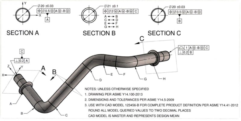
cmart,
I understand the preference to keep the drawing simple.
However, if the drawing is to be interpreted per a dimensioning and tolerancing standard such as ASME Y14.5, the issue with the directly toleranced angle 90°±3° between datum features A and B is that the datum feature simulators - the devices used to fixture the part and simulate the datum axes at inspection (contracting internal cylinders if the ODs are the datum features referenced regardless material boundary or expanding shafts referenced regardless material boundary if the IDs are the datum features), have no defined angular relationship. If a geometric tolerance such as perpendicularity is used to control the angular relationship, the 90° angle is understood to be a basic dimension without even being specified on the drawing. Then the angle between the simulators is 90°, as accurate as fixtures are built. However, when the drawing requires 90°±3° as shown, one problem is that the requirement is not quite clear regarding how to obtain the axes, and the second thing is that the value of 90° has no unique meaning. Sure, it's right in the middle of the allowed range, but officially it's nothing special and doesn't define the relationship between datum feature simulators. The dimension and tolerance could as well be defined as "87°+6°/-0°" or "87°-93°" and that would not make any difference. So officially you could have various fixtures without a way to know which are correctly made, which is usually not a good thing.

