Hi!
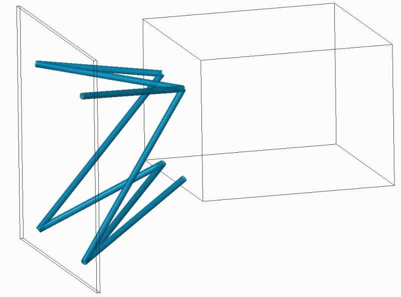
I'm currently doing a project where i'm constructing a framework for an engine mount connecting an airplane with an engine. The project involves both calculations by hand and with CAD(Creo), and i have no problem with the CAD part as i have done the simulations.
The part with doing calculations by hand have caused some problems where i'm doing the calculations in 3-D, and its causing some problems.
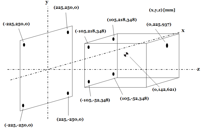
The top and bottom diagonals are not to be considered in the calculation by hand. Therefore you have 6 symmetrical beams.
So far what I have done in the calculations is that i've created a equation system with help of directional cosines which seems to get me the wrong answers. So i'm looking for some help in creating the equations system for this problem.
I'm currently doing a project where i'm constructing a framework for an engine mount connecting an airplane with an engine. The project involves both calculations by hand and with CAD(Creo), and i have no problem with the CAD part as i have done the simulations.
The part with doing calculations by hand have caused some problems where i'm doing the calculations in 3-D, and its causing some problems.
The top and bottom diagonals are not to be considered in the calculation by hand. Therefore you have 6 symmetrical beams.
So far what I have done in the calculations is that i've created a equation system with help of directional cosines which seems to get me the wrong answers. So i'm looking for some help in creating the equations system for this problem.