Continue to Site

Eng-Tips is the largest engineering community on the Internet

Intelligent Work Forums for Engineering Professionals

  • Congratulations Danlap on being selected by the Eng-Tips community for having the most helpful posts in the forums last week. Way to Go!

Force calculation Scissor lift retractable Chimney

Status
Not open for further replies.

Wolberto

Student
Dec 23, 2020
3
Hello,

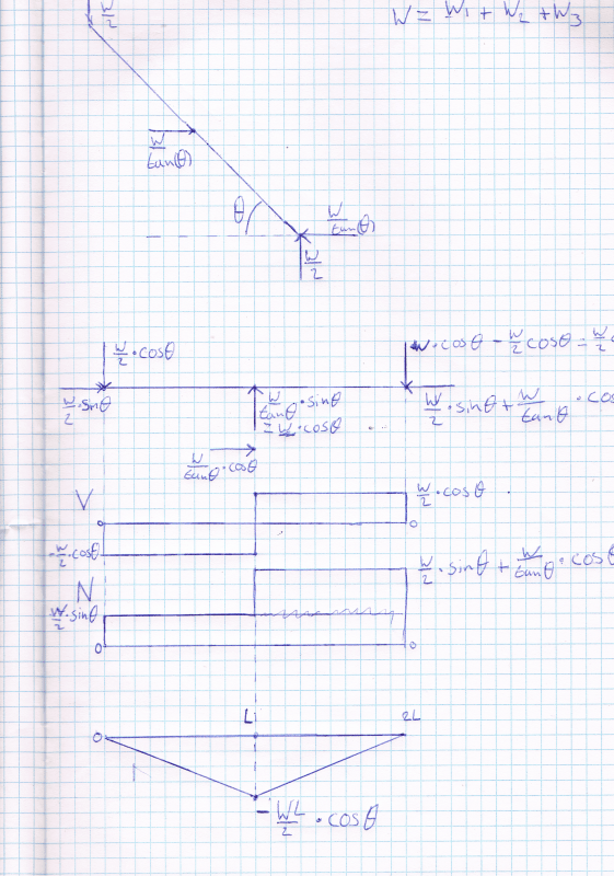
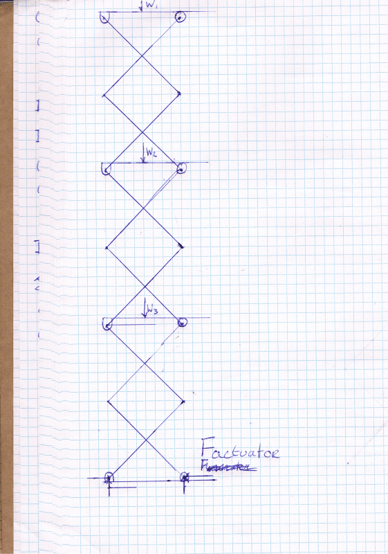
For an internship I and a fellow student are designing a retractable chimney. For the mechanism to retract the chimney, we chose a scissor mechanism. We already drew a large part of the chimney in solidworks and know we want to calculate the reaction forces and internal forces that are on the scissor arms and actuator. Can anyone help us?

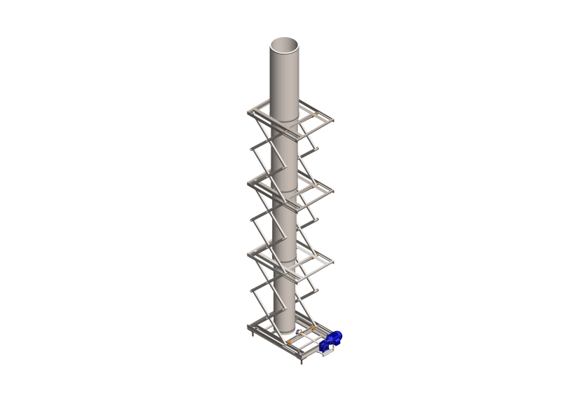
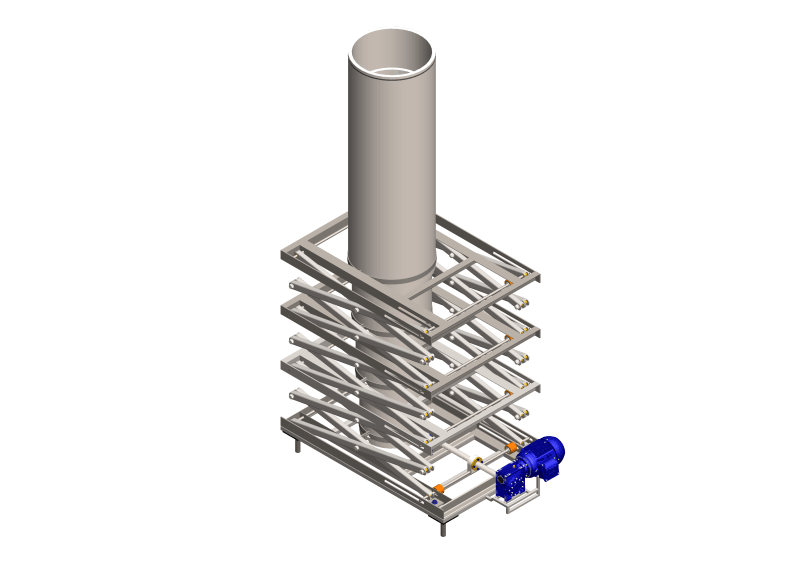
These are the images of the chimney
Hoofdassembly_V2.0_isometric_uitgeklapt_jdjnp0.png

Hoofdassembly_V2.0_isometric_ingeklapt_jzscgr.png

CCI06012021_00001_z0fo9b.png
 
Replies continue below

Recommended for you

The structure, as drawn, is unstable.

Edit #1: The chimney seems a little top heavy with the diameters increasing on the way up. It would seem preferable to have them decreasing on the way up, putting the stronger sections where they are needed to resist wind moment. That poses a problem of how they can be connected to the lifting device. Have you given any thought to how that might be accomplished?

Edit #2: Is there a demand for retractable chimneys? It seems to me that it would be more economical to simply build the chimney full height and forget about the retractable feature. The lifting apparatus would have to be there as long as the chimney remains in service, and doesn't add anything to the aesthetics, so far as I can see.

BA
 
@BAretired,

The chimney will discharge the fumes produced by a backup heating system and will only be used less then 500 hours per year. The Chimney has to be 7 meters to have an high enough dilution factor. The chimney has te retract to about 2,5 meters to be out of sight when the backup system is not active.

Our "client" said we didn't have to take economics into account and agreed with our plan. It is more of a school project than a real internship.

The upper segment will have a bigger diameter, so that fumes will not leak between the gaps of the segment (because the fumes rise) and rainwater wil not leak between the segment(because they drop down). Also there will be an chimneyhood installed on the top.

Here is a picture of what I mean:
CCI08012021_00000_2_mumysh.png


Kind regards,
Wobbe
 
@MacGyverS2000,

Yes, I understand that.

I used this site to calculate the reaction forces in the lowest arms:
My assumption was that I could just sum up weights 1,2 and 3, but I am not sure.

Then I drew the diagrams of the shear force, normal force and bending moment of the lowest arms:
CCI08012021_00001_jz2wz6.png


So my questions are:
- Can I sum up the weights and simplify the Free Body Diagram to only the lowest arms?
- If so, did I drew the diagrams right?

Kind regards,
Wobbe
 
Wolberto said:
The chimney will discharge the fumes produced by a backup heating system and will only be used less then 500 hours per year. The Chimney has to be 7 meters to have an high enough dilution factor. The chimney has te retract to about 2,5 meters to be out of sight when the backup system is not active.

Okay, that sounds reasonable. Your first pic shows four sections. Each section would need to be 1.75m long plus overlap.

Is it your expectation that wind and seismic forces would be resisted by the telescopic chimney, acting as a cantilever, which means that it provides lateral support to the scissor mechanism; or the chimney would be laterally supported by the scissor mechanism?

If the former, the telescopic sections must be loose enough to slide easily and tight enough to permit lateral forces and moments to be resisted without excessive deflection. If the latter, some serious thought would be required to determine how that could be achieved.

BA
 
Wolberto said:
- Can I sum up the weights and simplify the Free Body Diagram to only the lowest arms?
This is how you would get the reactions at the base, correct (by summing the weights)?
So, if you know the reactions at the base, you can "cut" the scissor lift off right at the base to create a FBD and determine the internal loads based on the reactions. This is the same approach that you are implying as well. Now, once you get above the first lift point, the forces in the arms would be different, but you could conservatively design them all for the loads they see at the base.

Obviously as BAretired is hitting on, this only takes care of the gravity load of the chimney, you still need to somehow resist the lateral loads. As it is a low use item there may be some argument to be made that the probability of it being up at the same time an earthquake happens is so low that you would not need to consider this as a design load. But, I would say you would need to consider some wind load.
 
Even without considering wind or seismic loading, I have a problem with gravity load. What is the capacity of the proposed structure to carry gravity load without buckling? Unless you are relying on the telescopic chimney to act as a continuous cantilever, there are no braced points in the scissor apparatus above ground level.

BA
 
Status
Not open for further replies.

Part and Inventory Search

Sponsor