Continue to Site

Eng-Tips is the largest engineering community on the Internet

Intelligent Work Forums for Engineering Professionals

  • Congratulations 3DDave on being selected by the Eng-Tips community for having the most helpful posts in the forums last week. Way to Go!

Flat Plate Bending Weld Stress

ENG2194

Mechanical
Sep 12, 2019
47
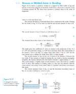
Hello, I have scenario where a flat plate is welded inside a ridged cylinder with top and bottom fillet welds all the way around and pressure on top. Im trying to figure out how to calculate the bending stress in the fillet welds. I was thinking I could approximate it like the following beam example where "b" is the circumference of the ID of the ridged cylinder. However, even with this approximation I'm struggling to figure out what to use for "M". For clamped flat plate stress calculations the radial bending is calculated in terms of lbf-in/in then divided by plate thickness squared to get in terms of stress. Not sure what bending moment could be approximated as in terms of lbf-in to be able to fit in the beam weld stress equation below.

1747751505671.png1747751746728.png
 
Replies continue below

Recommended for you

To fit that specific model, you could use b as the full circumference and M as full circumference x moment/in. Or use b as 1" and M as moment/inch, should be the same.
If it's a code-related question, refer to the code in question for weld requirements.
That model assumes rigid support and flexible beam. If you consider the rotation of the cylinder wall, you would get lower weld stresses. So if you come up with unreasonable weld sizes, it can be refined.
 
Could you provide a sketch. I think you are saying you have a flat plate installed in a pipe in the center and from one end to the other, such that it splits the top and bottom evenly into two compartments. The upper compartment is pressurized so that it causes bending of the plate and bending and shear in the welds. Is this correct?
 
Could you provide a sketch. I think you are saying you have a flat plate installed in a pipe in the center and from one end to the other, such that it splits the top and bottom evenly into two compartments. The upper compartment is pressurized so that it causes bending of the plate and bending and shear in the welds. Is this correct?
Yes that is correct. Im also curious about having only an upper fillet weld. With just an upper fillet weld would "d" just become "h"?
 
Not sure I understand the "ridged cylinder". Sketch?

If there's just an upper fillet isn't that a pinned rather than moment connection?

Is the pressure high enough to fall within ASME Section VIII Division 1 and thus you should follow the details and rules in UG-34?
 
It has been a while since I did weld design but this is how I see it.

With weld on top and bottom I would look it as the plate being a fixed beam with shear V and moment M in the equations shown above determined by the fixed beam formula.

With weld only at top I would consider only shear exists in the weld as determined by a simply supported beam model as the single welds at ends will act as a pinned connection that cannot support a moment as indicated by Geoff. So shear V will only exist and stress will exist only per equation a.
 
I have scenario where a flat plate is welded inside a ridged cylinder with top and bottom fillet welds all the way around and pressure on top. Im trying to figure out how to calculate the bending stress in the fillet welds

I want to understand the word 'ridged' is rigid. Assuming the cylinder is relatively rigid if compared with the stiffness of the circular plate , the support assumption ' clamped edge ' is reasonable.

I looked to the Theory of plates and shells ( TIMOSHENKO )
The expressions for radial and tangential moments are ;
1747821516044.png
In this case , the bending stress at the edge would be Mr and at the edge and r=a Mr would be Mr=(-q*a**2/8).
Check your weldment bending and shear stresses for unit width.
 
Last edited:
Is the plate installed along the length of a cylindrical pipe section or is it installed across the diameter of the cylinder? If along the length it would be a rectangular shape and what I describe is I believe how you would model. If across the diameter it would be a circular plate and I believe then you would need to use Roarks or Timoshenko like HTURKAK indicated to find the end moments.
 
If you’re welding in a circular plate, you could use the equations in Roark. The cylinder rotational support can be used by equating cylinder and circular plate gradients at the intersection. The cylinder will be modelled by two cylinders, one pressurised, the other not. Again, equate gradients at the intersection.
 
The welding configuration looks a bit strange to me. I could not locate any similar acceptable weld configuration in Sec VIII or B31.1 (assuming codes will be applicable). It is more conventional to cut the pipe and insert a blinding plate with flanges. Specifically, I have the following apprehensions:

1. Unless there is good access, it will be difficult to align the plate correctly inside the pipe. Similarly, it may be difficult to inspect and test.
2. Since this will be a blind spot, there may be corrosion that will be difficult to check.

Considering the moments given by @HTURKAK , you need to consider the weld area with throat thickness as reference for calculating the stresses. Also, the weld joint efficiency factors as per the code need to be considered.
 

Part and Inventory Search

Sponsor